Table of Contents
Advertisement
Advertisement
Table of Contents

Subscribe to Our Youtube Channel
Summary of Contents for ULTRA TEC ULTRAPOL Advance
- Page 1 ULTRAPOL Advance (3250.1) Lapping and Polishing Machine User Manual (3255.1) Issue 2.3 (Updated June, 2017) 1025 E Chestnut Ave Santa Ana, CA 92701 Toll Free (US) 1 877 542 0609 Tel: 1 714 542 0608 Fax: 1 714 542 0627 e-mail: info@ultratecusa.com www.ultratecusa.com...
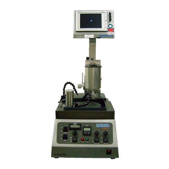
- Page 2 **Note: System shown above is complete with the Ultracollimator system.
- Page 3 Regulatory Agency Certification The Ultrapol Advance (Part Number ) has been tested and certified to meet the guidelines of 21 CFR 1040.10 and 1040.11 for CDRH Compliance. The Ultrapol Advance is a Class IIIa laser autocollimator assisted device that incorporates a number of CDRH mandated safety features, including but not limited to an emission indicator and chassis interlocks to bring the manufacturer into compliance with U.S.
-
Page 4: Table Of Contents
Optional Services / supplies ........................- 3 - INSTALLATION AND OVERVIEW ......................- 4 - Installing Ultrapol Advance ........................- 4 - Operating the Ultrapol Advance Safely...................... - 7 - Overview of Functions ..........................- 8 - Operator Controls/Features ........................- 11 - Work holders and Accessories ......................... -
Page 5: Introduction
INTRODUCTION A. Scope of Use ULTRAPOL advance is a self-contained lapping and polishing machine capable of preparing wide range of materials and sample types for subsequent use in various forms of microscopy, production and R&D. B. Parts List – What’s included... -
Page 6: Labels And Warnings
U.S. Because laser light is a form of radiation, it is monitored by CDRH, and we at Ultra Tec Manufacturing, Inc. have an obligation to the government, to ourselves and most importantly, to our customers to ensure that our products adhere to these regulations. -
Page 7: Suggested Services / Supplies
Aperture Warning: Located on the front of the Ultracollimator LCD Box just below the monitor and perpendicular to the aperture. AVOID EXPOSURE Laser radiation is emitted from this aperture Access Panel and Safety Interlock Warning: Located on rear panel of the Ultracollimator LCD box. DANGER Laser radiation when open. -
Page 8: Installation And Overview
II. INSTALLATION AND OVERVIEW A. Installing Ultrapol Advance Mechanical The main hardware is shipped as two items; the Base Unit and the Mast Head assembly. The Base Unit should be placed on a flat, sturdy bench. The Mast Head assembly may then be installed on the Base Unit, by use of the ‘base lock lever’... - Page 9 Electrical The voltage of the Ultrapol Advance unit is switch able 110/220V unless otherwise stated by means of a label on the machine. Select the proper input voltage via the selector switch on the back of the base unit.
- Page 10 Ultracollimator Installation** **If equipped The Ultracollimator may be shipped in 2 pieces, the Ultracollimator box and “L” bracket, or in one piece, “L” bracket already secured to the Ultracollimator box. Attach “L” bracket onto the back of the ULTRAPOL advance mast using the 4 screws provided for each side. Plug the power of the Ultracollimator box ONLY to the back of the Base labeled 110V.
-
Page 11: Operating The Ultrapol Advance Safely
U.S. government regulations Safety Precautions All persons who use the Ultrapol Advance or will be in the area where the Ultrapol Advance is in use should be aware of the potential hazards associated with the equipment. -
Page 12: Overview Of Functions
C. Overview of Functions It’s a good idea to familiarize yourself with the Ultrapol Advance for future reference in the instructional part of this manual. Baser Unit Main Power switch Sample rotation On/Off switch and speed knob Sample oscillation On/Off switch and speed knob... - Page 13 Mast/Head Assembly Handle for Z direction micro-adjust m. Locking screw for slippable scale Slippable scale Floating head lock Mast position lock Load control knob Analog dial height indicator Lift lever Tilt/quick release interface Tilt knobs Quick release lock - 9 -...
- Page 14 Ultracollimator System (Optional feature) w. LCD Screen menu button Input Video 2 Input Video 1 LCD Power ON/OFF aa. Y-axis crosshair adjustment bb. Beam Brightness cc. X-axis crosshair adjustment dd. Beam ON/OFF switch ee. Ultracollimator shutter/attenuator ff. Second X-axis crosshair adjustment gg.
-
Page 15: Operator Controls/Features
D. Operator Controls/Features Power ON/OOF switch (a). To stop/reset timer, pressing “Stop” during cycle will turn the lap, rotation and oscillation motion OFF. To adjust cycle time, press the buttons under each digit of the timer to desired cycle time. Pressing the Start button while the timer is Timing will reset the countdown. -
Page 16: Work Holders And Accessories
E. Work holders and Accessories Standard Quick Release Plate (6170.1) Optical line of sight The Standard QR Holder, allows for rapid transfer of sample between polisher and microscope. The plate is held in position on the machine by means of a cam lock. The alignment channel on the bottom of the holder means that the plate is mounted at the same rotational position. - Page 17 Order Code SEM Style & Type 6172.H Hitachi-compatible QR Holder & optical Stub 6175.H Hitachi Stub only (stainless steel) 6178.H Hitachi Stub only (aluminum) 6176.1 Hitachi X-sectioning Stub only (aluminum) 6172.P Philips-compatible (XL30) QR Holder & optical Stub 6175.P Philips Stub only (stainless steel) 6178.P Philips Stub only (aluminum) 6172.J...
- Page 18 iii. Encapsulated Mount Holder The encapsulated mount holder allows the polishing of samples that have been encapsulated. The three screws hold the potted samples in place. There are two magnets that hold an optical flat in place so that the holder can be used with the Ultracollimator. To do so, simply place the optical flat in place and mount the sample into the holder.
-
Page 19: Calibration
III. CALIBRATION A. Mechanical Alignment Aligning the base plate to the Aluminum platen. 1. Place a desired lap onto the Advance. Preferably one that does not have any film attached to it. 2. Place the micrometer into the hole on the side of the work holder and tighten the set screw so that micrometer is fixed in its position. - Page 20 8. Rotate the head to the 9 o’clock position and observe the deflection at the two positions for the x- axis (left and right). 9. If there is a height difference at the 9 o’clock position, adjust with the back screws on the base plate until there is no difference in height between the two X-axis positions.
- Page 21 tightening screws first, then adjust the set screws to bring the deflection on the micrometer to read ‘100.’ 16. Rotate back to the 12 o’clock position. If the deflection is not at ‘100’ adjust the Z micro-adjust on top of the head to bring the deflection to ‘100’ 17.
- Page 22 7. Turn the rotation switch to ON and dial speed to 1. Press START. Stop at the first (right) tilt knob location. If the readout on the micrometer is not at ‘100’ adjust the tilt knob to bring the micrometer needle to ‘100.’...
-
Page 23: Optical Alignment (Ultracollimator)
B. Optical Alignment (Ultracollimator) When the ULTRACOLLIMATOR is installed or after the ULTRAPOL advance system has been moved or reseated, the following procedure should be followed: Mount a sample with a reflective surface onto work holder (puck). Mount work holder into quick release holder. -
Page 24: Aligning Sample For Parallel Polishing With The Ultracollimator
When mounting a bare die to the sample holder (puck), make sure that the sample has a reflective backside. If it is not reflective, the Ultracollimator will not be able to detect the reflected light. A quick hand polish on a 3μm film will achieve the shiny surface needed. Mount sample directly above the center hole of the sample holder. -
Page 25: Load Control
C. Load Control (With no work holder in place) Release the up lock on the right side of the head so that the head is in the down position (do not allow the head to fall to lowest position, but lower it gradually). Turn pressure control knob clockwise(CW) until the center-shaft reaches the bottom stop and thus becomes heavy. -
Page 26: Correcting For Observed Tilt During Polishing
D. Correcting for Observed Tilt during polishing If you notice a tilt on the die, simply align the tilt knobs to west and east as you previously did in aligning your sample. Turning the tilt knob clockwise (CW), you are pushing the sample holder forward which translates to the side of the sample on the same side as the knob to DESCEND. -
Page 27: Applications
V. APPLICATIONS A. Topside Delayering of Single Die IC’s Parallel Delayering Techniques The standard lap for delayering used on the Advance is the 8 inch polyurethane lap. This is used with 0.05μm colloidal silica slurry. Make sure to have the drain plugged in the gray basin using the rubber plug, otherwise fluid will drain. - Page 28 Zeroing the scale on the Z-micro adjust With sample mounted to work holder and in the quick release holder with a lapping plate in place. Zero out the dial indicator while the head has not touched the lap. This is your zero point where the sample has not touched the lap.
-
Page 29: Cross-Sectioning Of Die / Packages
ULTRA TEC designs, manufactures and provides advanced surface preparation equipment and consumables for both routine and custom applications. ULTRAPOL advance can be used for a wide range of lapping & polishing applications including: TEM and pre-FIB Thinning... -
Page 30: Preventative Maintenance
VI. PREVENTATIVE MAINTENANCE A. Clean Up At the end of each day, the user should clean the machine to ensure proper machine function. Empty/drain basin of any slurries. Clean and rinse basin. Clean and rinse lapping plate. If a Polyurethane lap (3208.8) has been used, it is often necessary to re-condition the lap (see 6.3) Flush recirculation pump (see 6.2) B. -
Page 31: Reconditioning The Polyurethane Lap (6208.9)
C. Reconditioning the Polyurethane Lap (6208.9) The lap should be reconditioned before the start of each day to ensure quality polishing. Start Water coolant with Stopper out of the recirculation tray (running to drain) or Fill basin with water (if system not connected to water and drainage) Place polyurethane padded lap into position. -
Page 32: Accessories, Consumables & Spares
VII. ACCESSORIES, CONSUMABLES & SPARES Lapping & Polishing Films 8” diameter Diamond Lapping and Polishing Films 8” (200mm) diameter 8” PSA Backed Discs 8” Plain Backed Discs Order No. Micron Size Quantity Order No. Micron Size Quantity M-8230-1 M-8430-1 M-8231-1 M-8431-1 M-8232-1 M-8432-1... - Page 33 6.5 inch LCD monitor, with Video Out (NTSC). Includes optical flat and mounting bracket for ULTRAPOL advance 3210.1 Trade-in Value against pre-return of MUTIPREP or older series ULTRAPOL unit (NOTE: To qualify, customer must purchase ULTRAPOL advance plus ULTRACOLLIMATOR ) – 6170.1 Standard QR Sample Holder for Microscopy preparations optical 6178.1...
- Page 34 (6-2239-1), and then covered by the Mylar film to be used. Special Note: ULTRA TEC is proud to operate a continuous product improvement policy. Items may vary in appearance or specification from those shown here. Many of the items discussed are protected by PATENT or are PATENT PENDING.
-
Page 35: Appendices
APPENDICES - 31 -... -
Page 36: Appendix A - Timer Manual
Appendix A – Timer Manual Timer Manual Time Range Indicator I/O Status Indicators Illuminates to show the time base: H Illuminates to display when an input for hours, M for minutes, and S for or output is active: “IN” for the start seconds. - Page 37 First Operation: Determines whether the Repeat Cycle will start with an ON or an OFF Operation. (This parameter will only appear if Repeat Cycle is chosen as the Operating Function. Interval Time: Sets the amount of time the output will be active after the On Delay function has timed out.
- Page 38 Front Panel Reset Enable: When active (On), the timing operation can be reset in Operation Mode by simultaneously pressing the “E” and “P” keys. If inactive (Off), the timing operation can only be reset through the remote input. Security Level: 4 different levels of security are available: •...
-
Page 39: Appendix B - Ce Certification
Declares that the product: PRODUCT TYPE: Laboratory Sample Preparation Tool MODEL: ULTRAPOL Advance (Order Code 3250.1) Conforms to the following Application of Council Directive: LVD Directive EN61010-1 EMC Directive: 89/336/EEC EN61326:1998 Product Specific Standard Laboratory, Measurement, and Process Control Equipment Standards by which conformity has been established: EN55011.98... -
Page 40: Appendix C - Wiring Diagram
Appendix C – Wiring Diagram ULTRAPOL ADVANCE +12VDC 12V COM Inner/Striped Outer Motor 1/8 hp Control Board P/N 102301 Red Stop 3 Position Switch Button P/N 101884 P/N 103141 Core Green Start Button Outer P/N 102670 Potentiometer 75k O Bridge 2-9...
Need help?
Do you have a question about the ULTRAPOL Advance and is the answer not in the manual?
Questions and answers