Advertisement
Quick Links
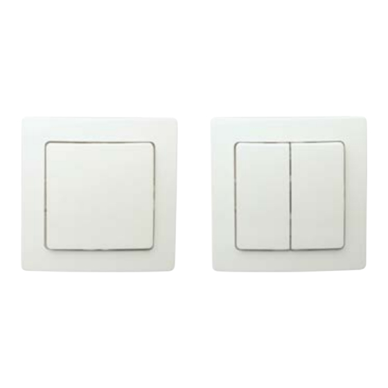
P P E-KNX-2P / P P E-KNX-4P /
P P E-KNX-2P-2G / P P E-KNX-4P-2G
LightMaster Switch Range
INSTALLATION MANUAL
Features
• This device is designed for use on KNX TP1 communication bus as a:
• Rocker switch
• Or single key pushbutton.
• The switch is available in 2 or 4 positions in either single or double
gang variants.
Important Notes
Read Instructions – We recommended that you read this Installation
Manual prior to commencement of installation.
Special P rogramming – T o e nable f ull f unctionality t he d evice i s r equired
to program using ETS software.
Installation Location – Install in a dry location, close to the equipment
to be interfaced with.
Panel interconnect ribbon cables – Maximum recommended length is
0.5 metre. They shall be double insulated and segregated from mains
and load cables in accordance to the local wiring code.
WARNING
ISOLATE FROM MAINS SUPPLY PRIOR
TO INSTALLATION OR SERVICING. NO USER
SERVICEABLE PARTS INSIDE. INSTALLATION
AND SERVICE BY QUALIFIED PERSONNEL
ONLY
• This device must only be installed and configured
by a qualified professional.
• Connect to KNX TP1 bus only following KNX
installation rules and local wiring code.
• KNX T P1 bus must be isolated and segregated from
mains and other wiring as per the local wiring rules
and KNX installation recommendations.
• Do not expose this device to rain or moisture.
Install in a dry location, indoors only.
• Do not open the device! For service inquiries
contact Philips Lighting.
•
•
•
Advertisement

Related Manuals for Philips LightMaster P1PE-KNX-2P


Summary of Contents for Philips LightMaster P1PE-KNX-2P
- Page 1 Special P rogramming – T o e nable f ull f unctionality t he d evice i s r equired to program using ETS software. Installation Location – Install in a dry location, close to the equipment to be interfaced with. Panel interconnect ribbon cables – Maximum recommended length is 0.5 metre. They shall be double insulated and segregated from mains and load cables in accordance to the local wiring code. WARNING • ISOLATE FROM MAINS SUPPLY PRIOR • TO INSTALLATION OR SERVICING. NO USER SERVICEABLE PARTS INSIDE. INSTALLATION AND SERVICE BY QUALIFIED PERSONNEL • ONLY • This device must only be installed and configured by a qualified professional. • Connect to KNX TP1 bus only following KNX installation rules and local wiring code. • KNX T P1 bus must be isolated and segregated from mains and other wiring as per the local wiring rules and KNX installation recommendations. • Do not expose this device to rain or moisture. Install in a dry location, indoors only. • Do not open the device! For service inquiries contact Philips Lighting.
- Page 2 4. If using a double Gang Switch, i.e. Part P1PE-KNX-4P- 2G or P1PE-KNX-2P-2G, connect the bus ribbon cable Front Cover Finishes between the two modules. Arctic White 5. Insert switch into the wall box or mounting box and secure with mounting screws. Do not over-tighten. Button Colours Arctic White 6. Snap faceplate into place. Environment -5º to 45ºC operating ambient temperature -25º to 55ºC storage temperature 0% to 90% RH non condensing Compliance CE, KNX Materials Plastic housing Protection Class IP20 Dimensions Single Gang Bezel H 83mm x W 83mm Two Gang Bezel H 150mm x W 83mm Max Group Addresses – EIB/KNX Back View P1PE-KNX-2P / P1PE-KNX-4P / P1PE-KNX-2P-2G / P1PE-KNX-4P-2G Installation Manual Rev D May 2012 Specifications subject to change without notice. © Not to be reproduced without permission. Unit 6, 691 Gardeners Road Mascot 2020 Australia. ABN 33 097 246 921 www.philips.com/knx • knx.info@philips.com...
Need help?
Do you have a question about the LightMaster P1PE-KNX-2P and is the answer not in the manual?
Questions and answers