
Related Manuals for TechnipFMC Smith Meter microLoad.net

Summary of Contents for TechnipFMC Smith Meter microLoad.net
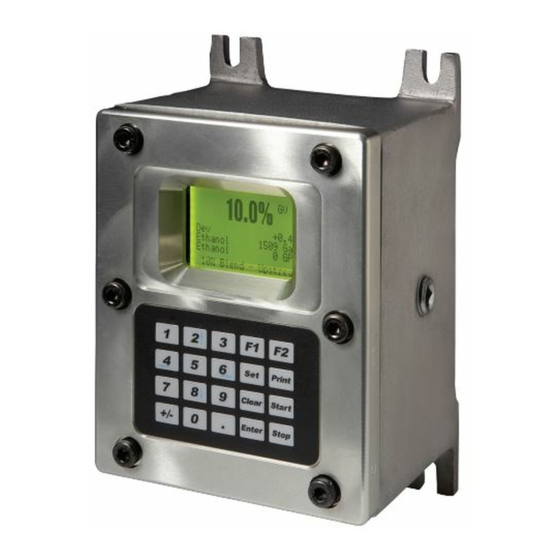
- Page 1 MANUAL Electronic Preset Delivery System Smith Meter microLoad.net ® ™ Installation Manual Bulletin MN06150 Issue/Rev 0.7 (9/18)
- Page 2 Disclaimer TechnipFMC Measurement Solutions, Inc. hereby disclaims any and all responsibility for damages, including but not limited to consequential damages, arising out of or related to the inputting of incorrect or improper program or default values entered in connection with the microLoad.net.
- Page 3 If damage has occurred during shipment or parts are missing, a written report should be submitted to the Customer Service Department, TechnipFMC Measurement Solutions, Inc., 1602 Wagner Avenue, Erie, Penn- sylvania 16510.
-
Page 4: Table Of Contents
Table of Contents Section I – Introduction ............................6 Section II – Pre-Installation Considerations ......................7 Mechanical ................................8 Electrical ................................8 Section III – Installation ............................10 Mechanical ................................10 Electrical ................................10 Start-Up ................................11 Section IV – Diagrams ............................12 Pulse Inputs ................................16 Wiring Diagrams ..............................17 Analog Inputs ..............................26 Communications ..............................27 Promass Coriolis Meter Communications ......................34... - Page 5 Tables and Figures Tables Table 1. Typical Wire Sizes ............................8 Table 2. Maximum Cable Length and Baud Rate (EIA-232) ..................8 Table 3. Maximum Cable Length and Baud Rate (EIA-485) ..................8 Table 4. Wiring Checklist .............................10 Table 5. MNET Board Terminal Assignments .......................15 Table 6.
-
Page 6: Section I - Introduction
Section I – Introduction Introduction This manual is to be used for the installation of the Smith Meter ® microLoad.net Electronic Preset Controller with ™ microLoad.net firmware. The manual is divided into six sections: Introduction, Pre-Installation Considerations, Installation, Diagrams, Specifications, and Related Publications. “Pre-Installation Considerations”... -
Page 7: Section Ii - Pre-Installation Considerations
Section II – Pre-Installation Considerations The Smith Meter ® microLoad.net is a micro-processor based single arm, single product electronic preset instrument ™ that supports up to 12 recipes. It is configurable to support a variety of user applications. Pulse Input EIA-232/EIA-485 Flow Meter Supervisory Computer,... -
Page 8: Mechanical
Section II – Pre-Installation Considerations An important pre-installation consideration is the se- Note: The following recommendations are based on our knowledge of the electrical codes. The local electrical codes should be reviewed lection of the ancillary equipment to be used with the to ensure that these recommendations follow the local code. - Page 9 Section II – Pre-Installation Considerations earth grounded. The grounding point should be as 8. All user wiring is terminated at compression-type close to the unit as possible. To ensure proper earth screw terminal strips. These terminal strips may be ground: removed from the microLoad.net MACF and MNET circuit boards to facilitate ease of wiring.
-
Page 10: Section Iii - Installation
Section III – Installation Mechanical IEC IEC Designation (IEC-HR03), with a maximum capacity of 1.5 Ah at a 1 h discharge rate. 1. Mount the microLoad.net using four (4) 5/16 - 18 Caution: To prevent ignition of hazardous atmo- bolts. See Figure 2 for mounting hole layout. spheres, disconnect from supply circuit before opening, keep tightly closed when circuits are in 2. -
Page 11: Start-Up
Section III – Installation hazardous atmospheres and to prevent electrical shock, Table 4. Wiring Checklist disconnect from supply circuits before opening, keep Install Pulse Input Wiring (from Meters and Metered tightly closed when circuits are in operation. Injectors) Install Pulse Outputs Wiring ... -
Page 12: Section Iv - Diagrams
Section IV – Diagrams Inches (mm) 1/2" NPT Conduit Connection 1/2" NPT Conduit Connection 7.36 9.65 (245) (187) 3.69 3.69 (94) (94) 2.50 2.50 (64) (64) Two (2) 3/4" NPT Conduit Connection 5.70 Mounting (145) 8.63 Hole (219) Layout 2.50 (64) 2.38 (60) -
Page 13: Figure 3. Opening Microload.net
Section IV – Diagrams Figure 3. Opening microLoad.net Issue/Rev. 0.7 (9/18) ║ MN06150 • Page 13... -
Page 14: Figure 4. Mnet Board
Section IV – Diagrams Figure 4. MNET Board Switch “S2” Functions Switch 1: Reserved (must be OFF) Switch 2: ON activates firmware upgrade on power up Switch 3: See below Switch 4: See below Switch 5: ON resets security password on power up Switch 6: Reserved (must be OFF) Note: Factory setting for all S2 switches is OFF Switch 3... -
Page 15: Table 5. Mnet Board Terminal Assignments
Section IV – Diagrams Table 5. MNET Board Terminal Assignments Connector: CN1 Connector: CN5 Terminal # Description Terminal # Description COM2 232Tx 485Tx- Meter Pulse Input/Channel A + COM2 485Tx+ Meter Pulse Input/Channel A - COM2 232Rx 485Rx+ Factory Use Only - Do not connect COM2 485Rx- Factory Use Only - Do not connect... -
Page 16: Pulse Inputs
Section IV – Diagrams Table 6. microLoad.net I/O Configuration Worksheet Page 16 • MN06150 ║ Issue/Rev. 0.7 (9/18) -
Page 17: Wiring Diagrams
Section IV – Diagrams MNET Board MNET Board PRIME 4 PRIME 4 WHITE WHITE 1 A+ 1 A+ BLACK 2 A- BLACK 2 A- YELLOW YELLOW 5 Shield 5 Shield 6 B+ 7 B- 3 +12Vdc 3 +12Vdc 4 Gnd 4 Gnd Prime 4, Single Pulse Prime 4, Dual Pulse... -
Page 18: Figure 6. Wiring Diagram, Pex-P Transmitter Single Pulse
Section IV – Diagrams MNET Board PEX-P BLACK 1 A+ WHITE 2 A- 5 Shield 3 +12Vdc 4 Gnd PEX-P, Dual Pulse Figure 6. Wiring Diagram, PEX-P Transmitter Single Pulse PEX-P Wire Codes: Black: Signal Red: +12 Vdc White: Common Note: Pulse Inputs •... -
Page 19: Figure 7. Wiring Diagram, Pps Transmitters
Section IV – Diagrams MNET Board MNET Board 1 A+ 1 A+ 2 A- 2 A- 5 Shield 5 Shield 3 +12Vdc 3 +12Vdc 4 Gnd 4 Gnd PPS, Dual Pulse PPS, Single Pulse Figure 7. Wiring Diagram, PPS Transmitters PPS Terminal Connections: 1. -
Page 20: Figure 8. Wiring Diagram, Pa-6 Transmitters
Section IV – Diagrams MNET Board MNET Board PA-6 PA-6 1 A+ 1 A+ 2 A- 2 A- PA-6 5 Shield 5 Shield 3 +12Vdc 3 +12Vdc 4 Gnd 4 Gnd PA-6, Single Pulse PA-6, Dual Pulse Figure 8. Wiring Diagram, PA-6 PA-6 Terminal Connections 1: Common 3: Signal... -
Page 21: Table 7. Promass Modeling For Single Pulse Wiring
Section IV – Diagrams Promass 80, 83, and 84 When connecting the Promass 84 (does not apply to the Promass 80 or 83 models) to a microLoad.net it is impor- tant that the “Line Monitoring” function on the Promass 84 be disabled. This is because the pulse input circuitry of the microLoad.net requires the input pulse “off”... -
Page 22: Figure 9. Wiring Diagram, Promass Coriolis Meter
Section IV – Diagrams MNET Board MNET Board Promass Promass 1 A+ 1 A+ 23/25 2 A- 2 A- 22/24 5 Shield 5 Shield 6 B+ 7 B- 3 +12Vdc 3 +12Vdc 4 Gnd 4 Gnd Promass, Single Pulse Promass, Dual Pulse Figure 9. -
Page 23: Figure 10. Wiring Diagram, Universal Pulse Transmitter (Upt)
Section IV – Diagrams MNET Board MNET Board 1 A+ 1 A+ 2 A- 2 A- 5 Shield 5 Shield 6 B+ 7 B- 3 +12Vdc 3 +12Vdc 4 Gnd 4 Gnd UPT, Dual Pulse UPT, Single Pulse Figure 10. Wiring Diagram, Universal Pulse Transmitter (UPT) UPT Terminal Connections: 1. -
Page 24: Figure 11. Wiring Diagram, Open Collector Output
Section IV – Diagrams Figure 11. Wiring Diagram, Open Collector Output The Pulse input circuitry has 1.6 kΩ of correct limiting resistance “built in” so that an external pull-up resistor is not required when an open collector output device is connected as shown. Page 24 •... -
Page 25: Figure 12. Wiring Diagram, Typical Metered Injector
Section IV – Diagrams Figure 12. Wiring Diagram, Typical Metered Injector The Pulse input circuitry has 1.6 kΩ of correct limiting resistance “built in” so that an external pull-up resistor is not required when an open collector output device is connected as shown. Issue/Rev. -
Page 26: Analog Inputs
Section IV – Diagrams Figure 13. Analog Inputs; Resistance (RTD) / 4-20ma If using two twisted pairs of wires, RTD+ and RTD- should be wired with one twisted pair. Sig+ and Sig– should be wired with another twisted pair. This input requires a four-wire connection to a platinum sensor with the following specification: 1. -
Page 27: Communications
Section IV – Diagrams Figure 14. General Wiring for Serial Communications Note: The shield is to be terminated at the communications device as shown. Note: If using RS-485, refer to switch termination information on page 14. Issue/Rev. 0.7 (9/18) ║ MN06150 • Page 27... -
Page 28: Figure 15. Multiple Microload.net Serial Communications
Section IV – Diagrams Figure 15. Multiple microLoad.net Serial Communications The figure shows the typical wiring scheme for multi-drop communications between a communications device and multiple microLoad.nets. The last microLoad.net in a multi-drop scheme must have the Receive Terminators enabled. These terminators are asserted by placing the appropriate switches of “S1”... -
Page 29: Figure 16. Rs-232 Shared Printing
Section IV – Diagrams Figure 16. RS-232 Shared Printing Issue/Rev. 0.7 (9/18) ║ MN06150 • Page 29... -
Page 30: Figure 17. Rs-485 Shared Printing
Section IV – Diagrams Figure 17. RS-485 Shared Printing Page 30 • MN06150 ║ Issue/Rev. 0.7 (9/18) -
Page 31: Figure 18. Microload.net Ethernet Communications
Section IV – Diagrams Figure 18. microLoad.net Ethernet Communications microLoad.net RJ-45 Terminations The microLoad.net and the associated RJ-45 connector located in the MNET board is designed as an “Ethernet Device”. When connecting to a distributive system through an Ethernet switch/hub or wireless bridge, a straight through T-568B cable is utilized. -
Page 32: Table 9. Wiring Termination For T-568B And T-568A
Section IV – Diagrams Table 9. Wiring Termination for T-568B and T-568A Color Code Abbreviation T-568B Pin T-568A Pin white w/orange stripe wht/org orange white w/ green stripe wht/grn blue white w/ blue stripe wht/blu green white w/brown stripe wht/brn brown Figure 19. -
Page 33: Figure 20. Lubrizol Eia-485 Additive Injector Communications
Section IV – Diagrams Figure 20. Lubrizol EIA-485 Additive Injector Communications Note: Lubrizol labels their EIA-485 communication ports with respect to what needs to be connected to their terminals and not with what the terminal represents. For example, the terminal labeled Tx- on the Lubrizol injector is actually Rx-, but Lubrizol intends for it to represent where you connect Tx- of the communicating device. -
Page 34: Promass Coriolis Meter Communications
Section IV – Diagrams MNET Board 1 Tx- TX + / RX + 2 Tx+ 3 Rx+ TX - / RX - 4 Rx- Promass Figure 21. Promass Coriolis Meter Communications (RS485) Programming Parameter microLoad Promass Baud Rate 38400 38400 Parity 8/No Parity/2 Stop bits No Parity, 2 Stop bits... -
Page 35: Digital Inputs
Section IV – Diagrams Digital Inputs The microLoad.net is capable of providing three DC digital inputs. The inputs can be programmed as to function through the configuration directory. Figure 22. DC Digital Inputs Issue/Rev. 0.7 (9/18) ║ MN06150 • Page 35... -
Page 36: Digital Outputs
Section IV – Diagrams Digital Outputs The microLoad.net is capable of providing two DC digital outputs and four AC digital outputs. The outputs can be programmed as to function through the configuration directory. Figure 23. DC Digital Outputs Page 36 • MN06150 ║ Issue/Rev. 0.7 (9/18) -
Page 37: Figure 24. Ac Digital Outputs
Section IV – Diagrams Figure 24. AC Digital Outputs Issue/Rev. 0.7 (9/18) ║ MN06150 • Page 37... -
Page 38: Instrument Power Wiring
Section IV – Diagrams Voltage Selector Switch TB2: Factory Cable Fuse 115 Vac Customer Neutral CN1: Factory Cable Wiring Safety Ground TB1: Instrument Power Voltage Selector Switch TB2: Factory Cable Fuse 230 Vac Customer CN1: Factory Cable Wiring Safety Ground TB1: Instrument Power Figure 25. -
Page 39: Sample Application Wiring
Section IV – Diagrams Sample Application Wiring The following is a sample microLoad.net configuration. Our sample application includes the following equipment: • Smith Meter microLoad.net™ ® • PD meter w/ UPT transmitter • Smith Meter Card Reader ® • Serial Printer •... -
Page 40: Figure 26. Sample Application Worksheet
Section IV – Diagrams Figure 26. Sample Application Worksheet Page 40 • MN06150 ║ Issue/Rev. 0.7 (9/18) -
Page 41: Figure 27. Sample Application Ac Wiring
Section IV – Diagrams Figure 27. Sample Application AC Wiring Issue/Rev. 0.7 (9/18) ║ MN06150 • Page 41... -
Page 42: Figure 28. Sample Application Dc & Signal Wiring
Section IV – Diagrams * Isolated open collector output. Limit to <10mA. Figure 28. Sample Application DC and Signal Wiring Page 42 • MN06150 ║ Issue/Rev. 0.7 (9/18) -
Page 43: Figure 29. Sample Application Power Wiring
Section IV – Diagrams Figure 29. Sample Application Power Wiring Issue/Rev. 0.7 (9/18) ║ MN06150 • Page 43... -
Page 44: Section V - Appendix A: Atex Installation
Section V – Appendix A: ATEX Installation Standards used: IEC 60079-0 6th Edition, EN 60079-0: 2012 +A11:2013, UL 60079-0 6th Edition, CAN/CSA C22.2 No. 60079-0:11 IEC 60079-1 6th Edition, EN 60079-1: 2007, UL 60079-1 6th Edition, CAN/CSA C22.2 No. 60079-1:11 IEC 60079-11 6th Edition, EN 60079-11: 2012, UL 60079-11 6th Edition, CAN/CSA C22.2 No. -
Page 45: Section Vi - Related Publications
Section VI – Related Publications The following literature can be obtained from TechnipFMC Measurement Solutions Literature Fulfillment at measure- ment.fulfillment@fmcti.com or online at www.fmctechnologies.com/measurementsolutions. When requesting literature from Literature Fulfillment, please reference the appropriate bulletin number and title. microLoad.net Application Bulletin (LACT/Loading/Unloading)................Bulletin AB06100 Specification ............................ - Page 46 Measurement Solutions, Inc. Germany Operation 500 North Sam Houston Parkway West, Smith Meter GmbH Regentstrasse 1 Suite 100 TechnipFMC.com 25474 Ellerbek, Germany Houston, Texas 77067 USA P:+49 4101 304.0 P:+1 281.260.2190 © TechnipFMC 2018 All rights reserved. MN06150 Issue/Rev. 0.7 (9/18)
Need help?
Do you have a question about the Smith Meter microLoad.net and is the answer not in the manual?
Questions and answers