Table of Contents
Advertisement
Quick Links
Advertisement
Table of Contents

Subscribe to Our Youtube Channel
Related Manuals for Hiwin SEG-04

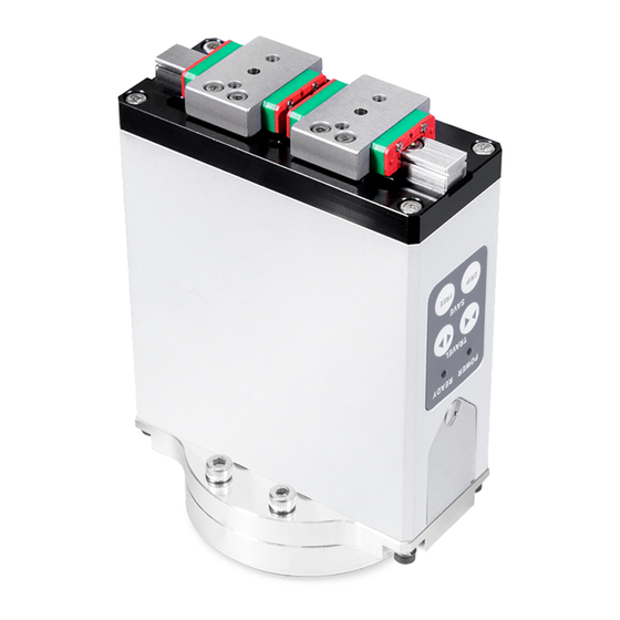
Summary of Contents for Hiwin SEG-04
- Page 1 Integrated Electric Gripper User Manual Original Instruction RoHS www.hiwin.tw...
- Page 2 INDUSTRIE 4.0 Best Partner Multi-Axis Robot Pick-and-Place / Assembly / Array and Packaging / Semiconductor / Electro-Optical Industry / Automotive Industry / Food Industry • Articulated Robot • Delta Robot • SCARA Robot • Wafer Robot • Electric Gripper • Integrated Electric Gripper •...
-
Page 3: Table Of Contents
3.5 Error status descriptions (SEG-24 only)................... 3.6 Function descriptions (SEG-24 only) ..................3.7 NPN/PNP mode adjustment teaching ..................4. Dimension drawing ........................ 18 4.1 SEG-04 outline drawing ....................4.2 SEG-24 outline drawing ....................4.3 STG-16 outline drawing ....................5. Safety certification ........................ 20 6. -
Page 4: Precautions (Be Sure To Read Before Use)
C11UE01-1907 Precautions (be sure to read before use) 1.1 Safety regulations Indicates an imminently hazardous situation which, if not avoided, will Danger: result in death or serious injury. Indicates a potentially hazardous situation which could result in death Warning: or serious injury, if the equipment is operated incorrectly. Indicates a potentially hazardous situation which may result in injury Caution:... - Page 5 C11UE01-1907 equipment to ensure safety. When operating or ◎ Please do not disassemble, or modify the product adjusting the gripper, be sure to observe safety to avoid personal accident, electric shock, fire or measures for the system. damage. Warning ◎ Do not expose the product to radiant heat safety circuit emergency stop button.
-
Page 6: Warning Label Location And Description
C11UE01-1907 ◎ Fixture should be designed to be light and short. design characteristics will affect the maximum workpiece weight. ◎ Fixture material, shape, clamping area and other 1.2 Warning label location and description The product will be labeled as shown below to ensure correct and safe operation. Danger, do not insert finger here Danger, do not insert... -
Page 7: Warranty Coverage
◎ Damage caused by any natural disaster. i.e., fire, earthquake, tsunami, lightning, windstorms, floods etc. HIWIN does not provide any warranty or compensation to all the damage caused by above-mentioned circumstances unless the user can prove that the product is defective. -
Page 8: Product Characteristics
• High speed clamping - SEG-04 open/close cycle time is 0.26 seconds, suitable for 3C industry high-speed pick and place operations. - SEG-24 Clamp has smart pick and place function, set to function keys that store clamping point. It can move to clamping point at high-speed and automatically convert to slow clamping, effectively reduce cycle time and increase efficiency. -
Page 9: Application Examples
Electronic components Glass crystal products Light bulb Rubber and plastic resin Capacitor Glass test tube Suitable for clamping in a narrow space Object column 2.3 Specification Model SEG-04 SEG-24 STG-16 Category Item Unit Value Stroke per side Gripping force 8 [Note1]... -
Page 10: System Architecture Diagram
For more details, please refer to ch6.4 design guide of gripping section. [Description 5] SEG-04 can only inside grip inside and the backlash is 0.5mm per side. Don’t grip at the backlash area. 2.4 System architecture diagram... -
Page 11: Specification Illustration
According to the output mode (NPN, PNP type) of the gripper, the sensor with corresponding output mode is provided. [Note 2] For SEG-24 and STG-16. [Note 3] Please refer to HIWIN official website "TM quick installation guide". https://www.hiwin.tw/download/tech_doc/ee/TM_Plug&Play_Version.pdf [Note 4] Please refer to HIWIN official website "UR+ Technical Manual Guide". -
Page 12: Electric Grippers Mounting Methods
A. When using the screw holes on underside of gripper body Mounting direction Mounting direction 固定方向 固定方向 Mounting direction Mounting direction 固定方向 固定方向 Locating pins 定位銷 Concentric collar 同心軸環 SEG-04 SEG-24 Mounting direction Mounting direction Mounting direction 固定方向 固定方向 固定方向 固定方向 定位銷 Locating pins 同心軸環 定位銷... - Page 13 C11UE01-1907 Type Screw M Recommended locking torque T (N*m) SEG-04 M3x0.5P 0.6~0.8 SEG-24 STG-16 M5x0.8P 2.8~3.4 C. When using screw holes on the back of gripper body Mounting direction Mounting direction Locating pin Locating pins 定位銷 Mounting direction 固定方向 位銷...
-
Page 14: Control Method
C11UE01-1907 Control method 3.1 Input/output definitions and functional descriptions • • SEG-04, STG-16 I/O control:2IN/1OUT SEG-24 I/O control:2IN/2OUT Signal input Signal input Function Function None None Open Open Close Close Signal output Signal output Function Function OUT1 Busy OUT1 Busy... -
Page 15: External Wiring Instructions
White Ready Brown DIR (O/C) Green OUT1 Busy Yellow 24V/0.5A Blue OUT2 Alarm [Note 1] Black Shielding [Note 1] SEG-24 only. SEG-04 SEG-24 NPN Type PNP Type NPN Type Ready Ready Ready OUT1 Busy OUT1 Busy OUT1 Busy Load Load... -
Page 16: Operation Timing Diagram
C11UE01-1907 3.4 Operation timing diagram • SEG-04, STG-16 IN1 (Ready) Close IN2 (DIR) Open OUT1 (Busy) Close Open • SEG-24 IN1 (Ready) Close IN2 (DIR) Open OUT1 (Busy) Open Reset Close 3.5 Error status descriptions (SEG-24 only) After the GRIP point and the FREE point are set completely and Ready=ON, please refer to the table below:... -
Page 17: Function Descriptions (Seg-24 Only)
C11UE01-1907 3.6 Function button descriptions (SEG-24 only) Panel Press button Mode Short press Long press Move inward Jog button (inward) Move inward 1 mm continuously Jog button Move outward Move outward 1 mm (outward) continuously Gripping center Tolerance Memory button point (G) (G+n or G-n) Clear all storage... - Page 18 C11UE01-1907 • Setup process Ready OFF Press at the same time Reset Be sure to perform Reset after powering up 3 Sec. Clear all stored points LED Blue Depends on user's requirements to setup Blinks 3 times Gripping center LED Blue Blinks1 times 3 Sec.
-
Page 19: Npn/Pnp Mode Adjustment Teaching
C11UE01-1907 3.7 NPN/PNP Mode Adjustment Teaching • SEG-24 SEG-24 electric gripper is set default to NPN mode at the factory. If user required PNP mode, please follow the steps below to adjust them. Step Image Description Please unscrew the two hexalobular screw (1) at the side of the electric gripper. - Page 20 C11UE01-1907 • STG-16 STG-16 electric gripper is set default to NPN mode at the factory. If user required PNP mode, please follow the steps below to adjust them. Step Image Description (1) (2) Please unscrew the four Phillips screws (1) at the end of the electric gripper, and flip open the electric gripper rear cover (2).
-
Page 21: Dimension Drawing
C11UE01-1907 Dimensions 4.1 SEG-04 outline drawing 4.2 SEG-24 outline drawing... -
Page 22: Stg-16 Outline Drawing
C11UE01-1907 4.3 STG-16 outline drawing 6-M2x0.4Px4.5DP 6-Ø6h7 6-Ø4.5 Connector Cable: Straight Type Detail A 3-Ø9.5 6-M4x0.7Px6DP B.C.DØ56 (50) 2-M5x0.8Px5DP 5.75 Right-angle Type ±0.05 +0.02 Ø4 x2DP 0.00 27.6 2-M3x0.5Px3DP Detail B +0.02 x3DP 0.00 ±0.05 27.75 3-M6x1Px6DP B.C.DØ56... -
Page 23: Safety Certification
C11UE01-1907 Safety Certification CE Compliance Machinery Directives 2006/42/EC Low Voltage Directives (LVD) 2014/35/EU EN ISO 12100:2010 Safety of Machinery EN 60204-1:2006+AC:2010 EN 61000-6-2:2005 Electromagnetic Compatibility Directives (EMC) EN 61000-6-4:2007+A1:2011 Hazardous Substances Restriction Directives (RoHS) 2011/65/EU... -
Page 24: Appendix
Most end effectors are assembled with robot arm. This section provides the basic functions of a robot language example for reference. Robot Arm Model: HIWIN RA605 Robot arm control program: HRSS 2.1 Gripper type: SEG-24 corresponds to Robot I/O as shown below ●... - Page 25 C11UE01-1907 If gripper wants to execute following actions ▼ Gripper "RESET" ▼ Robot arm "Move to point P1" ▼ Gripper "Grip" (Grip item) ▼ Robot arm "Move to P2" ▼ Gripper "Release" (release item) User can refer to the bottom of the robot language 1.
-
Page 26: Accessories Installation Methods
C11UE01-1907 6.3 Accessory installation methods • SEG-04 sensor installation SEG-04 SEG-04 Sensor - assembly exploded diagram Sensor - assembled product diagram SEG-04 sensor accessory kit Item Name Amount S4 sensor rack Bolt (M4X0.7PX6L SUS) S4 sensor plate Bolt (M2X0.4PX6L SUS) Proximity switch [Note 1] [Note 1] Refer to table below for proximity switch specifications. - Page 27 C11UE01-1907 • SEG-04 with RA605 robot manipulator SEG-04 & RA605 - Assembly explosion diagram SEG-04-RA605 accessory kit Item Name Amount Positioning pin (Ø5X8L) S4-605 Robot manipulator adapter Inner hexagon head screws (M5X0.8PX8L SUS) Positioning pin (Ø3X10L) S4-605 Gripper adapter Bolt (M3X0.5PX8L SUS) Bolt (M3X0.5PX8L SUS)
- Page 28 C11UE01-1907 • SEG-24 sensor installation SEG-24 SEG-24 Sensor - assembly exploded diagram Sensor - assembled product diagram SEG-24 sensor accessory kit Item Name Amount S24 sensor rack Bolt (M4X0.7PX6L SUS) S24 sensor plate Bolt (M2.5X0.45PX4L SUS) Proximity switch [Note 1] [Note 1] Refer to table below for proximity switch specifications.
- Page 29 C11UE01-1907 • SEG-24 with RA605 robot manipulator SEG-24 & RA605 - Assembly explosion diagram SEG-24-RA605 accessory kit Item Name Amount Positioning pin (Ø5X8L) S24-605 Robot manipulator adapter Bolt (M5X0.8PX8L SUS) Gripper adapter Bolt (M3X0.5PX10L SUS) S-605HRS cable...
- Page 30 C11UE01-1907 • STG-16 sensor installation STG-16 STG-16 Sensor - assembly exploded diagram Sensor - assembled product diagram STG-16 sensor accessory kit Item Name Amount T16 sensor rack Bolt (M3X0.5PX4L SUS) T16 sensor plate Bolt (M2X0.4PX4L SUS) Proximity switch [Note 1] [Note 1] Refer to table below for proximity switch specifications.
- Page 31 C11UE01-1907 • STG-16 with RA605 robot manipulator STG-16 & RA605 - Assembly explosion diagram STG-16-RA605 accessory kit Item Name Amount Positioning pin (Ø5X8L) T16-605 Robot manipulator adapter Bolt (M5X0.8PX10L SUS) Positioning pin (Ø4X6L) Bolt (M5X0.8PX10L SUS) S-605HRS cable...
-
Page 32: Finger Design Guide
6.4 Finger design guide SEG-04 is a light gripping force gripper. If the finger is made of metal material, such as steel and aluminum etc., the finger could be pasted with soft material to increase the friction, such as rubber and Polyurethane etc. -
Page 33: Electric Gripper Option Selection Requirements Table
C11UE01-1907 6.5 Electric gripper option selection requirements table Company Contact Date name person Telephone Address Fax. E-Mail Pre-selected Effective stroke gripper spec. (mm) Repeatability Gripping force (N) (mm) Gripping speed Material (mm/s) Weight (kg) Size (mm) ... - Page 34 3. HIWIN will not sell or export products or processes restricted under the "Foreign Trade Act" or related regulations. Export of restricted products should be approved by proper authorities in accordance with relevant laws and shall not be used to manufacture or develop nuclear, biochemical, missiles or other weapons.
- Page 35 Mega-Fabs Motion Systems, Ltd. CHICAGO, U.S.A. SINGAPORE HAIFA, ISRAEL www.hiwin.com www.hiwin.sg www.mega-fabs.com info@hiwin.com info@hiwin.sg info@mega-fabs.com HIWIN Srl BRUGHERIO, ITALY www.hiwin.it info@hiwin.it Copyright © HIWIN Technologies Corp. ©2019 FORM C11UE01-1907 The specifications in this catalog are subject to change without notification. (PRINTED IN TAIWAN)
Need help?
Do you have a question about the SEG-04 and is the answer not in the manual?
Questions and answers