Table of Contents
Advertisement
Advertisement
Table of Contents

Summary of Contents for Kolmeks NC 209
- Page 1 riable peed ntroller Operating manual manNC_eng_30...
-
Page 2: Table Of Contents
Index 1. NC Introduction ................................. 3 2. Safety Instructions ................................3 3. Technical Characteristics ..............................4 3.1 Weight and dimensions ................................5 4. Electric wiring ..................................6 4.1 Protections ..................................... 12 4.2 Electromagnetic compliance ..............................12 4.3 Installation with long motor cables ............................12 5. -
Page 3: Nc Introduction
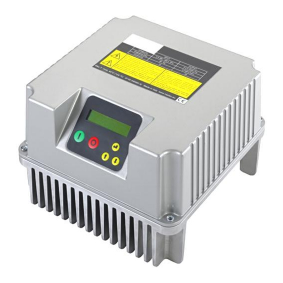
1. NC Introduction NC is a variable frequency drive designed to control and protect pumping systems by varying the output frequency to the pump. NC can be applied to both new and existing pumping systems, and provides: energy and cost savings ... -
Page 4: Technical Characteristics
Max I in Max I out Model Vin +/- 15% [V] power* Size [kW] 1 x Vin NC 209 1 x 230 3 x Vin 1 x Vin NC 214 1 x 230 3 x Vin NC 218 1 x 230... -
Page 5: Weight And Dimensions
3.1 Weight and dimensions Weight * Size SIZE 2 SIZE 1 Model [Kg] NC 209 NC 214 NC 218 NC 225 NC 306 NC 309 NC 314 NC 318 NC 325 NC 330 SIZE 3 NC 338 NC 348 NC 465... -
Page 6: Electric Wiring
4. Electric wiring Power board NC 209,214 Power supply: Output: 230 V AC auxiliary fans LINE: L1, L2,GND 3 ph motor: (wall mounting kit) It is recommended to use GND,U,V,W, FAN: F1, F2 cable lugs 1 ph motor: earth, U (running), V (common) It is recommended to use cable lugs. - Page 7 Power board NC 218, 225 Power supply: Motor output: 12 V dc auxiliary fans (wall mounting kit) LINE: L1, L2, GND MOTOR: U, V, W, GND VENT: +, - It is recommended to use cable It is recommended to use cable WARNING: respect the polarity.
- Page 8 Power board NC 306,309,406,409 Power supply: Motor output: 12 V dc auxiliary fan (wall mounting kit) : LINE: GND , L1, L2, L3, MOTOR: U, V, W, GND 0VE, + VE It is recommended to use cable It is recommended to use cable WARNING: respect the polarity.
- Page 9 Power board NC 314,318,325,330,414,418,425,430 Power supply: Motor output: 12 V dc auxiliary fans (wall mounting kit) LINE: L1, L2, L3, GND MOTOR: U, V, W, GND VENT: +, - It is recommended to use cable It is recommended to use cable WARNING: respect the polarity.
- Page 10 Power board NC 338,348,365,375,385,438,448,465,475,485 P.E. MOTOR LINE Power supply: Motor output: LINE: L1, L2, L3, P.E. MOTOR: U, V, W, P.E. It is recommended to use It is recommended to use cable lugs. cable lugs. Cable stripping recommended for line input and output to the motor.
- Page 11 Control board Analog inputs (10 or 15 Vdc): Digital outputs: RS485 for COMBO: AN1: 4-20 mA: sensor 1 motor run signal: AN2: 4-20 mA: sensor 2 NO1, COM1: closed contact with motor running. AN3: 4-20 mA / 0 - 10 Vdc (settable ...
-
Page 12: Protections
4.1 Protections The protections required upstream each NCs depends on the type of installation, and local regulations. We recommend to use overload protection with the characteristic curve of type C and type B circuit breaker, sensitive to both AC and DC current. -
Page 13: Nc Installation
5. NC installation NC can be installed directly on the fan cover of the motor or mounted on the wall. Motor mounting kit In this application NC is cooled by the motor fan. Motor kit (available upon request) allows a solid coupling of the two units and it is composed of: NC SIZE 1 NC SIZE 2... - Page 14 NC SIZE 3 n.° 1 motor feet adaptor for MEC160,180,200,225 n.° 4 M8 bolts, n.° 4 M10 bolts, nuts and washer...
- Page 15 In this application NC is cooled independently by its auxiliary cooling fan integrated in the radiator. Wall-mounted kit is composed of: NC SIZE 1 NC SIZE 2 n.° 1 auxiliary fan 230V AC (NC 209,214) or 12 n.° 2 12 V DC fans. VDC (NC 306,309,406,409) n.° 1 fans cover. ...
-
Page 16: Nc Installation For Constant Pressure Control
5.1 NC Installation for constant pressure control NC controls the pump speed to maintain constant pressure at a set point independent of the water demand in the system. A basic schematic is shown below: 1: pump 2: check valve 3: pressure tank 4: valve 5: valve 6: pressure sensor... -
Page 17: Nc Installation For Differential Constant Pressure Applications
5.2 NC installation for differential constant pressure applications NC can manage the pump speed in order to keep constant the pressure difference between the dischage and suction side of the pump in circulation systems. To do this, it is usually installed a differential pressure sensor. Alternatively, it is possible to use two identical pressure sensors: one in suction side and one in discharge side of the pump. -
Page 18: Nc Use And Programming
6. NC Use and Programming NC software is extremely simple to use, but allows a wide variety of parameters to be set for ideal system calibration. Setting Parameters are organized in 2 levels: 1: Installer level (MENU’ CONTROL PARAMETERS, MENU’ IN/OUT PARAMETERS, MENU’ CONNECTIVITY PARAM.) A password is required for this level;... - Page 19 XXXX XXXXXX Unit Unit XXXXX Type of motor connected: Motor type single phase (NC 209, 214) three-phase asynchronous three-phase XXXXXX synchronous PM (permanent magnets) Rated current of the motor per it’s nameplate indication increased Rated motor Amp.
-
Page 20: Foc Motor Control
If ON is selected, after a lack of voltage, NC returns to its normal Autorestart status; if NC was powering the pump before the voltage drop, it resumes powering the pump automatically. ON/OFF Warning, review the advice in chapter 1 Once the Setting procedure is completed you will get this indication INITIAL SETUP on the display;... - Page 21 The calibration process can take up to one minute. Wait until it has completed. The calibration process must be performed during the final electrical configuration of the system, i.e. with the motor, the cable and any filter applied. If there is any variation of the motor, cable or filter applied, it is necessary to repeat the calibration process by accessing the motor parameters menu (default password 002).
-
Page 22: Initial View
6.3 Initial view When first powering the NC, the display shows : release of display software (LCD = X.XX) and the release of inverter software (INV = X.XX) as shown below: LCD = X.XX INV = X.XX The following End User messages are displayed by pushing the scroll buttons: p is the pressure value read by the pressure transducer. -
Page 23: Menu View
First row gives the NC status: Inv: ON XXX.X Hz NC is powered and is powering the motor showing its frequency. Inv: ON Mot: OFF NC is powered but motor is not running (i.e. motor/pump was stopped due to minimum frequency being reached) ... - Page 24 Parameter Default Description Maximum value allowed in the system. If the readen value goes over this value, an Max alarm value alarm occurs and the pump is stopped. Pump is automatically restarted if the XXX.X [bar] readen value goes below the maximum value for a period of at least 5 seconds.
- Page 25 Parameter Default Description To ensure proper operation of pressure control is recommended to place the sensor near the pump. To compensate the pressure loss in the pipes (proportional to flow) it is possible to vary the pressure set in a linear relation with respect to frequency.
- Page 26 Parameter Default Description Delta control Value drop below the set value required to restart the pump during control ramp. XXX.X [bar] press. Set value Delta control Control ramp Stop delay Freq.min.control Min mot. freq Delta start Value drop below the set value required to start the pump from stop condition.
-
Page 27: Motor Parameters
Parameter Default Description Function to allow alternating between the NCs connected in COMBO (or pumps connected in DOL) in order to allow equal Alternance use of each pump in the group; master will reorganize the starting priority of the ON/OFF pumps by checking the life of each of them. - Page 28 Voltage boost Voltage increase during the motor start up. Warning: An excessive value can seriously damage the motor. Contact the XX.X [%] motor manufacturer for further information. Rated motor Amp. Rated motor current as per its nameplate indication increased by 5%. XX.X [A] Rated motor freq Rated motor frequency as per its nameplate.
- Page 29 V / f characteristic with which NC feeds the engine. The linear characteristic corresponds to constant torque with variable speed. The V/f lin. --> quad. quadratic characteristic is normally used with centrifugal pumps. The 85 % selection of torque characteristic should be done ensuring a smooth XXX [%] operation, a reduction of energy consumption and a lower level of heat and acoustic noise.
-
Page 30: In/Out Parameters
6.7 IN/OUT parameters Parameter Default Description Unit Unit [bar,%,ft,in,cm,m,K,F,C,gpm,l/min,m3/h,atm,psi] XXXXX F. scale sensor Sensor full scale. XXX.X Min.value sensor Sensor minimum value. XXX.X Zero correction for analog input 1 (4-20 mA) Offset input 1 (20 mA x 20% = 4 mA). Zero correction for analog input 2 (4-20 mA) Offset input 2 (20 mA x 20% = 4 mA). -
Page 31: Connectivity Parameters
Parameter Default Description Dig.In.2/3 delay Digital input IN2 & IN3 delay. Digital input IN1 has 1 second fix delay. 6.8 Connectivity parameters Parameters Default Description MODBUS address MODBUS address from 1 to 247 MODBUS baudrate 9600 MODBUS baudrate from 1200 bps to 57600 bps XXXXX [bps] MODBUS data format RTU N81... - Page 32 Check if the pump is primed Check the set value of dry running cosphi. Dry running cosphi is approximately 60% of the rated cosphi (at rated frequency) listed on the motor plate. If pump’s cosphi is lower than the set dry- Motor cosphi is lower than the set value of running cosphi for at least 2 seconds, NC stops NO WATER...
-
Page 33: Auxiliary Pumps During Constant Pressure Control
If pumps cosphi is lower than the dry-running cosphi for at least 2 seconds, NC will stop the pump. NC will try to run the pump every 10, 20, 40, 80, 160 minutes and then the pump is stopped. ATTENTION: if dry-running protection occurs, NC will try to start the pump automatically. Be sure to cut power supply before attempting maintenance NC will stop the pump if the input motor current is higher than the set motor current for an extended time. -
Page 34: Dol Pumps
8.1 DOL pumps Each DOL pump is switched on by a contactor controlled by the digital output DOL1 and DOL2 present in the NC. NC relays driving the DOL pumps are relays with no voltage contacts. Max voltage to the contacts is 250 V, max current 5 A. -
Page 35: Combo Function
External switch Max 240 VAC, 5 A MANUAL Max 30 VDC, 5A Contactor AUTO Motor digital output 8.2 COMBO function In the “Control parameters” menu it is possible to enable the COMBO function that allows serial communication between up to 8 NCs, each one connected to a pump. The operating principle (switch on/off) of pumps is similar to as stated in chapter 8.1. - Page 36 Master setup 1. Supply power to the NC master. 2. If not yet completed, perform the initial configuration as described on chapter 6.2 3. Initial view is shown: Inv: ON/OFF Mot: ON/OFF p_mis=XX.X [bar] 4. Scroll until: Menù ENT to access 5.
- Page 37 Slave setup Follow Master setup until point 11. In case of failure of master in a Combo system, will be replaced by slave. As a consequence, all parameters must be setup independently on each inverter, master mode. 1. Set: NC’s address in parallel operation. Address ...
-
Page 38: Trouble-Shooting Chart
9. Trouble-shooting chart LCD does not switch on after powering Check the connecting flat cable between the LCD board (attached to the NC the cover) and the control board Check the fuses Check that the power cables are properly connected. ... -
Page 39: Technical Assistance
10. Technical Assistance For more technical information contact the authorized reseller providing the following information. The solution to the problem will be found faster and easier if full information is provided. Model/Serial Code LCD version (shown when NC is power INV version (shown when NC is power supplied) supplied) - Page 40 DECLARATION OF CONFORMITY In according with: Machine Directive 2006/42/EC EMC Directive 2014/30/EU Low Voltage Directive 2014/35/EU R&TTE Directive 2014/53/EU NC is an electronic device to be connected to other electrical equipment with which it is to form individual units. It must, therefore, that the putting into service of this unit (with all its subsidiary equipments) to be performed by qualified personnel.
- Page 41 NOTE...
- Page 44 Copyright Kolmeks Oy The manufacturer reserves the right to modify informations in this manual without any notice.
Need help?
Do you have a question about the NC 209 and is the answer not in the manual?
Questions and answers