
Summary of Contents for Enlogic Advantage Series
- Page 1 Advantage Series Power Distribution Unit and Inline Energy Meter User Manual Version: 1.0...
-
Page 2: Table Of Contents
Connecting with Serial Connection ..............................21 Creating Unique Pinout Connection ..............................22 Connecting Sensors (Optional) ................................. 23 Section 3: enLOGIC Web User Interface (Web UI) ....................24 Supported Browsers ................................. 24 Logging in enLOGIC Web UI ............................. 24 Logging In ......................................24 Changing User Password .................................. - Page 3 Advantage Series User Manual Rack Location ....................................37 LED Edge Color ....................................38 Power Panel and Core Location ............................... 38 SNMP Management ..................................39 Email Setup ...................................... 43 Send Test Email ....................................44 Event Notification .................................... 44 Trap Receiver ....................................45 PDU Thresholds ....................................
- Page 4 Appendix A: Advantage Series Bracket Mounting Information ................92 Appendix B: Advantage Series Product Range for EMEA ..................93 Appendix C: Advantage Series Product Range for North America ................ 94 Appendix D: Firmware Update Procedures ......................95 USB Method ..................................95 Web Interface Method ..............................
- Page 5 Advantage Series User Manual List of Figures Figure 1:NMC Detail ..............................12 Figure 3: Power Menu Navigation ..........................16 Figure 4: Sensor Menu Navigation ..........................16 Figure 5: User Interface Control ..........................17 Figure 6: Circuit Breakers ............................17 Figure 7: Single-Phase Model ............................. 18 Figure 8: Three-Phase Model ............................
- Page 6 Advantage Series User Manual Figure 49: Circuit Breaker ............................49 Figure 50: Edit Circuit Breaker details ........................49 Figure 51: Control Management ..........................50 Figure 52: Edit Outlet Information ..........................50 Figure 53: Edit External Sensor Thresholds ........................ 51 Figure 54: Rack Access Control ........................... 52 Figure 55: Rack Access Control Add and Edit ......................
- Page 7 Table 9: Dev Commands Table 10: Pwr Commands Table 11: RNA Commands Table 12: Advantage Series Bracket Mounting Information Table 13: EN2000, EN5000 and EN6000 Series for EMA Table 15: EN2000, EN5000 and EN6000 Series for North America LOGIC- A division of CIS Global.
-
Page 8: Pdu Safety Guidelines
Advantage Series User Manual PDU Safety Guidelines This manual is intended for installers, maintenance professionals, and qualified users of enLOGIC power distribution units (PDUs). Keep this safety information for operation, installation, and maintenance of the PDU and accessory equipment. This product complies with the latest safety requirements for equipment and accessories for use in a rack mounting environment. -
Page 9: Table 1: Input Plug Type For Region Wise
Advantage Series User Manual Follow all local and national codes, when installing the PDU. The PDU should be connected to a dedicated circuit protected by a branch circuit breaker matching the PDU input plug-type for your region: Table 1: Input Plug Type for Region wise... -
Page 10: Section 1: Introduction
This manual is intended to assist in the installation and setup of the Advantage Series PDU. Refer to this manual to install properly and operate the Advantage Series PDU. It is recommended that the user must follow the procedures as outlined in this manual to assist in proper installation and prevent damage to the PDU and associated equipment. -
Page 11: Outlets
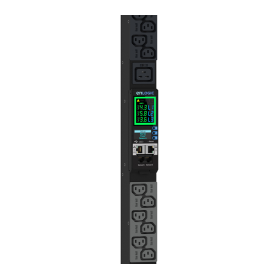
2 Color LED displays. As per the working image of the enLOGIC NMC, the EN2.0 range of PDUs now support two displays. The larger (LED) display provides spot power information, which is in full RGB color and always visible. This allows user to complete energy consumption spot checks at any given time. - Page 12 Sensor1/ Serial connection, Figure 1:NMC Detail Sensor2 There are 2 displays/5 ports on all standard advantage series models, as shown below. LED Graphical Alarm Icons: PDU Alarm, Cascade Error Alarm, Temperature Alarm, Security • Handle Alarm, and Circuit Breaker Alarm.
- Page 13 Advantage Series User Manual Figure 2: NMC Feature EN2.0 1 LOGIC- A division of CIS Global.
-
Page 14: Oled Display
The OLED display is located on front of the Advantage Series PDU above the connection ports. When an Intelligent device is operated for the first time, allow few minutes for onboarding to completely initialize the platform. -
Page 15: Setup Menu Navigation
Advantage Series User Manual Setup Menu Navigation Figure 4: Setup Menu Navigation Alarm Menu Navigation Setup Active Alarm Alarms Inactive Alarm Power Sensors Figure 5: Alarm Menu Navigation LOGIC- A division of CIS Global. -
Page 16: Power Menu Navigation
Advantage Series User Manual Power Menu Navigation Figure 2: Power Menu Navigation Sensor Menu Navigation Figure 3: Sensor Menu Navigation LOGIC- A division of CIS Global. -
Page 17: Menu, Select, Scroll And Reset Button
Circuit Breakers The enLOGIC EN2.0 Range of power product, which is rated above 20 A for North American region and above 16 A for international regions, do carry branch circuit hydraulic magnetic breakers. -
Page 18: Single-Phase Models
Advantage Series User Manual Single-Phase Models All Single-Phase model support hydraulic magnetic breakers that are color coded to the corresponding outlets. All Three-Phase model rated above 20 A and 16 A, will also use a color coding scheme, using 3 colors rather than 2 colors, Black, blue and grey. -
Page 19: Section 2: Installation
Before Installation Prepare the installation site: make sure that it is not exposed to extreme temperature or humidity and it. Make sure to allow space around the enLOGIC PDU for cabling and outlet connections. Note: enLOGIC PDUs are designed for maximum operating temperatures of 55–60°C (131–140°F). Refer to each model’s technical datasheet for specific information. -
Page 20: Mounting
PDU input-plug type. Note: When connecting the enLOGIC PDU to a Power Source, make sure that you have enough length in the PDU power cord to reach the PDU power source. -
Page 21: Connecting Pdu To Network
Connecting PDU to Network The enLOGIC EN2.0 range of PDUs are set to obtain an IP address via DHCP by default. Therefore, when an enLOGIC PDU is connected to a network for the first time, the PDU will automatically obtain an IP address. -
Page 22: Creating Unique Pinout Connection
192.168.1.100 255.255.255.0 192.168.1.1 Creating Unique Pinout Connection enLOGIC recommends to purchase our serial cable (EA9119) for use with the Advantage Series iPDU. This ensures an accurate connection. However, to create your own pinout connection for the RJ45 to... -
Page 23: Connecting Sensors (Optional)
Advantage Series User Manual Connecting Sensors (Optional) To enable the Advantage Series device to detect enLOGIC conditions, connect one or more sensors to the PDU sensor port 1 or 2. The maximum distance for sensor cabling, which is plugged into the device sensor port should not exceed 100 feet (30 m). -
Page 24: Section 3: Enlogic Web User Interface (Web Ui)
Advantage Series User Manual Section 3: enLOGIC Web User Interface (Web UI) The enLOGIC Web UI is used to manage, control, configure, and administrate the Energy series PDUs and accessories. Supported Browsers The enLOGIC Web UI is accessible from the below browsers: Firefox (v14.0.1 or higher) -
Page 25: Overview Of Enlogic Web Ui
Type your User Name and Password. • Click Log In button. Figure 11: Login Page Landing Page Below image shows the home page of the enLOGIC Web UI, after login. Figure 12: Landing Page LOGIC- A division of CIS Global. -
Page 26: Table 4: Menu Icon Description
Advantage Series User Manual Table 4: Menu Icon Description S.No Icon Description Click this Home icon to redirect/move to home page. Home page provides an overview of the PDU with access to the Dashboard, Identification, and Control & Manage. Click this icon to view and download the logs and data logs of the PDU. -
Page 27: Menu Dropdown
Advantage Series User Manual Menu Dropdown Below image shows some of the dropdown menus available in the enLOGIC Web UI. Figure 13: Menu Dropdown Navigating the Action Menus Dashboard In this page, the user can view information of total PDU, Load, Sensors and Energy. -
Page 28: Identification
Advantage Series User Manual Figure 15: Energy Information Identification • Go to Home Page -> Identification. • or click PDU GUI Home icon to dropdown the home menu and select Identification to view the information. Figure 16: Identification Information LOGIC- A division of CIS Global. -
Page 29: Control And Manage
Advantage Series User Manual Control and Manage Click PDU GUI Home icon to dropdown the home menu and select Control & Manage. Figure 17: Control and Manage PDU 2. Enable the Outlet Control Enabled radio button. 3. Click icon to edit/change the Outlet information below, •... - Page 30 Advantage Series User Manual View/Download/Clear Event Log Go to System Administration -> View Event Log. The View Event Log window opens. Figure 19: Event Log window Click the below options as required: Download Log: to download the logs • Clear Log: to delete/clear the logs.
- Page 31 Advantage Series User Manual View /Configure/Download/Clear the Data Log Go to System Administration -> View Data Log. The View Data Log window opens. Figure 21: Data Log window Select the below options as required: Data Log Configuration • Download Data Log •...
-
Page 32: Network Settings
Advantage Series User Manual Network Settings The EN Series PDU supports IPv4 and IPV6 with full featured network management and alerting capabilities. After you select your Internet protocol option, you will be able to communicate via HTTP, HTTPS, SNMP, FTPS and Email for network communications... -
Page 33: Change Link Speed
Advantage Series User Manual Change Link Speed Below are the steps to change the Ethernet link speed. Click Change Link Speed button. Select speed (as required below) from dropdown menu. • Auto Negotiation • 10/100 Mbps • 1 Gbps Click Save button to complete setting. -
Page 34: Syslog Configuration
Advantage Series User Manual Syslog Configuration Web/RESTapi Access Configuration By default, accessing EN Series PDU uses HTTP port setting. To change the HTTP port settings: Go to Network Setting -> Web/RESTapi Access Configuration. In the Web/RESTapi Access Configuration dialog box, type a new port number in the corresponding field. -
Page 35: Daylight Saving Time
Advantage Series User Manual Figure 31: Edit Options of NTP settings Daylight Saving Time Go to Network Setting -> Daylight Saving Time Setting. Enable radio button. Click Clock icon and select the time (required). Click Save button to complete setting. -
Page 36: System Management
Advantage Series User Manual System Management Below are the options, user can use to manage the system as necessary, • Upload Firmware: used to upload firmware details. • Upload Configuration: used to upload configuration details. • Download Configuration: used to download configuration details. -
Page 37: System Information
Advantage Series User Manual System Information Go to System Management -> System Information. Type System Name, Contact Name, Contact Email, Contact Phone and Contact Location in the required field. Click Save button to complete setting. Figure 34: Edit Options of System Information... -
Page 38: Led Edge Color
Advantage Series User Manual LED Edge Color LED Edge Color can be configured into 7 colors. • • Blue • White • Yellow • Green • Cyan • Pink The LED code on the panel will flash, when PDU is on. -
Page 39: Snmp Management
Advantage Series User Manual SNMP Management Simple Network Management Protocol (SNMP) is used to manage the Advantage Series PDU(s) remotely. SNMP allows the user to monitor and detect network faults and to even configure variable data in the PDU. (Refer Section 4: SNMP) - Page 40 Advantage Series User Manual Setup SNMP General Access the Web interface and login. Under the SNMP Management, select SNMP General. Click Edit button to update/change the details. Figure 44: SNMP General The SNMP General includes SNMP Access and Version. Enable the access, if required.
- Page 41 Advantage Series User Manual Define SNMP V1/V2c User Access the Web interface and login. Under SNMP Management, select SNMP V1/V2c Manager. Figure 48: Define SNMP V1/V2c User In the SNMP V1/V2c panel, select the SNMP V1/V2c manager to configure. Click the pencil icon to popup the Edit panel that shows the configurable options to make changes/updates.
- Page 42 Advantage Series User Manual Configuring Users for SNMP v3 Communications Access the Web interface and login. Under the SNMP Managers, select SNMP V3. Figure 50: SNMP V3 Manager Figure 51: SNMP V3 Edit In the SNMP V3 panel, select the SNMP V3 manager for configuration.
-
Page 43: Email Setup
Advantage Series User Manual Email Setup The EN Series PDU can be configured to send alerts or event messages via email using SMTP settings. This requires the SMTP settings that to be configured with an IP address for the SMTP server and a valid email address. -
Page 44: Send Test Email
Advantage Series User Manual Send Test Email You can send a test email to check the email is in active or not by using this feature. • Type the email address and then click Send button Figure 39: Send Test Email Event Notification Event notifications are situations in which the EN Series PDU notifies and reacts to certain conditions. -
Page 45: Trap Receiver
Advantage Series User Manual Trap Receiver SNMP (Simple Network Management Protocol) can be used to manage the EN Series PDU(s) remotely. SNMPV1 Trap receiver can be configured by typing in name, host and community. (Typically, the Read Community and Write Community are public). - Page 46 Advantage Series User Manual SNMP v3 protocol allows for encrypted communication. To enable SNMP v3 for a user, you must have SNMP Setting Privileges. Type Name, Host and Security Level to configure trap server. Select No Auth No Priv/Auth no Priv/Auth Priv from Security Level dropdown.
-
Page 47: Pdu Thresholds
Advantage Series User Manual PDU Thresholds To access the PDU Thresholds page, 1. Go to Home Page -> Settings. 2. Click on Thresholds, the PDU Threshold page opens. Edit Power Thresholds Below are the steps to change the Power Thresholds settings and alarm notifications, 1. - Page 48 Advantage Series User Manual Edit Input Phases Below are the steps to change the Input-Phase settings and alarm notifications. 1. Choose the Input Phases tab in the PDU Threshold page. 2. Click icon to do modification for Phase Current and Phase Voltage.
-
Page 49: Viewing Circuit Breaker Data
Advantage Series User Manual Viewing Circuit Breaker Data In this page, you can view the circuit breaker data such as bank, low and high critical, low and high warning. To view the circuit breaker data, 1. Choose the Circuit Breaker tab in the PDU Threshold page. -
Page 50: Control Management
Advantage Series User Manual Control Management The outlet Control Management is used to set the limits for warning or critical. 1. Choose the Control Management tab in the PDU Threshold page. 2. Click icon to do modification on, • Low Critical (W) •... -
Page 51: External Sensors
Advantage Series User Manual External Sensors The External Sensors section displays the connected sensors on the PDU. The following are information about the sensor that are shown in the identification page: Type • Name • Serial number • • PDU name •... -
Page 52: Handle And Compatible Cards Types
Advantage Series User Manual Figure 53: Rack Access Control Figure 54: Rack Access Control Add and Edit Handle and Compatible Cards Types Below are the card lists which are supported on the different swing handle, 1. MYFARE® Classic 4K 2. MYFARE® Plus 2K 3. -
Page 53: Smart Rack Control
Advantage Series User Manual Smart Rack Control To access the Smart Rack Control page, 1. Go to Home Page -> Settings. 2. Click on Smart Rack Control, the Smart Rack Control page opens. It is used to set up the access control server door Handle (above 4 Handle and Compatible Cards) that has lot of options. - Page 54 Advantage Series User Manual Figure 57: Edit Handle Settings Figure 58: Edit Status LED Settings Figure 59: Edit Remote Control LOGIC- A division of CIS Global.
-
Page 55: User Settings
Figure 60: Edit Beacon Settings Figure 61: Edit Keypad Settings User Settings The Advantage Series PDU comes with a standard Admin profile and a standard User profile. The Admin profile is typically the system administrator and it has the “Admin Role” with full •... -
Page 56: Add Users/Change Password
Advantage Series User Manual Figure 62: User Settings of Landing Page Add Users/Change Password. To create a new user profile: Click on the User Settings, the user settings page opens. Click on the icon, to create a new user profile. - Page 57 Advantage Series User Manual Figure 64: User Profile Modification Delete: To delete the existing user profile, 1. Go to User Settings. 2. Go to the username. 3. Select the next to the username to delete. LOGIC- A division of CIS Global.
-
Page 58: Ldap Server Settings
Advantage Series User Manual LDAP Server Settings To setup LDAP to access the Active Directory (AD) and provide authentication when logging into the PDU via the Web Interface: 1. Go to Device User Setting -> LDAP Configuration. 2. Select the LDAP Enable checkbox (Refer Figure 66: Edit LDAP Configuration). - Page 59 Advantage Series User Manual Figure 66: Edit LDAP Configuration Once the LDAP is configured, the PDU must understand for which group authentication occurs. A role must be created on the PDU to reference a group within Active Directory (AD). Within the Web Interface, go to User Settings -> Click on the Add Role button Type Role Name, which was created in AD i.e.
-
Page 60: Radius Configuration
Advantage Series User Manual Once LDAP authentication is ready to use. • To test this, click save, then click “LDAP Configuration” again and type Active Directory user name/password into the test box. • Click Test LDAP Configuration. If a box pops up with all green “SUCCEEDED” (no X’s), the LDAP is successfully configured. - Page 61 Advantage Series User Manual Figure 69: To Add Role LOGIC- A division of CIS Global.
- Page 62 Advantage Series User Manual To modify a custom user role: Select the role. click Edit Button. Edit the role name and privileges as needed. click Save. Figure 70 :Modify Custom User Role To delete a user role: Select the role.
-
Page 63: Session Management
Advantage Series User Manual Session Management Session management supports the users to manage the Sign-In retries, number of retries allowed, session timeout value and lockout time. • Click to setup the parameters. Figure 73: Session Management Figure 74: Edit Session Management... -
Page 64: Password Policy
Advantage Series User Manual Password Policy You can set a requirement for users to change their password at set intervals using the Password Aging Interval policy. You can also specify criteria for passwords to ensure that your users enter strong passwords. -
Page 65: Section 4: Snmp
Advantage Series User Manual Section 4: SNMP Simple Network Management Protocol (SNMP) is used to manage the Advantage Series PDU(s) remotely. SNMP allows the user to monitor and detect network faults and to even configure variable data in the PDU. -
Page 66: Loading The Mib File
Advantage Series User Manual Loading the MIB file Click on File -> select Load MIBs The Open window comes to view: 1. Select the latest version of the mib file 2. Click Open-> The mib file gets loaded. 3. The MIB Tree comes to view on the SNMP MIBs-> Expand the MIB Tree and select the iso.org.dod.internet... -
Page 67: Section 5: Redfish
Advantage Series User Manual Section 5: Redfish Redfish API is tested using POSTMAN, which is a Google Chrome extension app for GET, POST and DELETE method requests. 1. To setup the Redfish access, type the PDU IP in chrome and login to the PDU using the credentials. - Page 68 Advantage Series User Manual • Create a session using POST method: POST query the URL http://{pdu_ip}/redfish/v1/SessionService/Sessions along with the two headers (basic auth and json object type) and the body: "username":"admin", "password":"123456789" Figure 79: POST Request • Use the X-Auth Token from the response body along with the other two headers and basic authentication for any POST requests (Refer Figure 80).
-
Page 69: Redfish Urls Supported With Get Method
Advantage Series User Manual Figure 81: Delete Request Redfish URLs Supported with GET Method Session Service S.No https://<ip_addr>/redfish/v1/ /redfish/v1/SessionService /redfish/v1/SessionService/Sessions /redfish/v1/SessionService/Sessions/{session_ids} Account Service S.No /redfish/v1/AccountService /redfish/v1/AccountService/Accounts /redfish/v1/AccountService/Accounts/{username} /redfish/v1/AccountService/Roles /redfish/v1/AccountService/Roles/{rolename} Managers S.No /redfish/v1/Managers /redfish/v1/Managers/manager /redfish/v1//Managers/manager/NetworkProtocol /redfish/v1//Managers/1/LogServices /redfish/v1//Managers/1/LogServices/Log /redfish/v1//Managers/1/LogServices/Log/Entries Metrics S.No /redfish/v1/PowerEquipment/RackPDUs/{pdu_id}/Metrics Power Equipment S.No... - Page 70 Advantage Series User Manual /redfish/v1/PowerEquipment/RackPDUs/{pdu_id} Branches S.No /redfish/v1/PowerEquipment/RackPDUs/{pdu_id}/Branches /redfish/v1/PowerEquipment/RackPDUs/{pdu_id} /Branches/#cbnumber Outlets S.No /redfish/v1/PowerEquipment/RackPDUs/{pdu_id}/Outlets /redfish/v1/PowerEquipment/RackPDUs/{pdu_id}/Outlets/#outletnumber Sensor S.No /redfish/v1/PowerEquipment/RackPDUs/{pdu_id}/Sensors/Power{cbnum#} /redfish/v1/PowerEquipment/RackPDUs/{pdu_id}/Sensors/Current{cbnum} /redfish/v1/PowerEquipment/RackPDUs/{pdu_id}/Sensors/VoltageAL1N /redfish/v1/PowerEquipment/RackPDUs/{pdu_id}/Sensors/CurrentOUTLET# /redfish/v1/PowerEquipment/RackPDUs/{pdu_id}/Sensors/VoltageOUTLET# /redfish/v1/PowerEquipment/RackPDUs/{pdu_id}/Sensors/PowerOUTLET# /redfish/v1/PowerEquipment/RackPDUs/2/Sensors/EnergyOUTLET44 /redfish/v1/PowerEquipment/RackPDUs/2/Sensors/PowerMains1-6 /redfish/v1/PowerEquipment/RackPDUs/2/Sensors/CurrentMains1-3 /redfish/v1/PowerEquipment/RackPDUs/2/Sensors/VoltageMains1-6 /redfish/v1/PowerEquipment/RackPDUs/2/Sensors/FreqMains /redfish/v1/PowerEquipment/RackPDUs/2/Sensors/PDUPower Mains S.No /redfish/v1/PowerEquipment/RackPDUs/{pdu_id}/Mains /redfish/v1/PowerEquipment/RackPDUs/{pdu_id}/Mains/AC1 Redfish URLs Supported with POST Method S.No /redfish/v1/AccountService/Accounts...
-
Page 71: Event Service
Advantage Series User Manual Event Service Subscribe Event Service: 1. Using POST method, create a session and apply the generated X-auth-token to the headers. 2. Query the URL http://<pdu_ip_addr>/redfish/v1/EventService/Subscriptions using POST method with the following body: "destination":"http://<ip_addr>/redfish/v1/events", "events":"Alert", "context":"web", "protocol":"redfish"... -
Page 72: Section 6: The Command Line Interface
Advantage Series User Manual Section 6: The Command Line Interface The Command Line Interface (CLI) is an alternate method used to manage and control the PDU status and parameters, as well as basic admin functions. Through the CLI a user can: Reset the PDU •... -
Page 73: Cli Commands Table
Advantage Series User Manual CLI Commands Table The following is a list of commands available in the CLI to execute. The commands are divided into 5 main categories: System setting (sys), Network configuration (net), User setting (usr), Device setting (dev) and Power (pwr). -
Page 74: Table 7: Net Commands
Advantage Series User Manual EN2.0>sys log edit data on 5 sys log [del|edit] SUCCESS Edits the data log [event|data] configuration [on|off] interval EN2.0>sys log edit data off [interval] SUCCESS sys ledcolor [pduid]/all] EN2.0>sys ledcolor pduid dark [dark/red/green Update color of LED... - Page 75 Advantage Series User Manual Net Commands Description Example EN2.0>net ssh SUCCESS net ssh [on/off] Sets ssh on/off SSH Port: 22 SSH server is running EN2.0>net ftps SUCCESS net ftps [on/off] Sets ftps on/off FTPS Port: 21 Service is running Is Ftp EN2.0>net http...
- Page 76 Advantage Series User Manual EN2.0>net snmp SUCCESS v1v2c: ON net [snmp] v3: ON [v1v2c/v3/trap] trap: ON [on/off] EN2.0>net snmp v1v2c off SUCCESS net [mac/tcpip] Displays the mac EN2.0>net mac address, IPv4 SUCCESS MAC Addr: C8-45-44-66-2B-65 MAC Addr: C8-45-44-66-2B-67 EN2.0>net tcpip SUCCESS eth0 IPv4 Addr: 10.10.105.37...
- Page 77 Advantage Series User Manual net ip [v4] [v4v6] Sets ipv4 EN2.0>net ip SUCCESS IPV4 EN2.0>net ipv4 Reboot required for change to take effort IP protocol is changed, reboot to validate System Reboot now, Are you sure?(Y/N): net phy Set the link speed to EN2.0>net phy...
-
Page 78: Table 8: Usr Commands
Advantage Series User Manual Table 8: Usr Commands Usr Commands Description Example EN2.0>usr list SUCCESS Role Privilege Role ============================= usr list Lists out the PDU users ================ admin admin Administrator 1 user user User manager manager Administrator 3 EN2.0>usr login... -
Page 79: Table 9: Dev Commands
Advantage Series User Manual Table 9: Dev Commands Dev Commands Description Example EN2.0>dev daisy SUCCESS Daisy chain unit number: 1 Daisy chain address list: 0 0 0 Setting the PDU Daisy Mode: QNA dev daisy [rna/qna] Daisychain to RNA or... -
Page 80: Table 10: Pwr Commands
Advantage Series User Manual Downstream: 1 Upstream: 1 Mains: 1 PDU 3: Downstream: 1 Upstream: 1 Mains: 1 dev ehandle dev ehandle 1 hot lock [pduID] Enables ehandle [cold/hot] function [lock/unlock] Table 10: Pwr Commands Pwr Commands Description Example EN2.0>pwr unit 1... -
Page 81: Section 7: Sensors
The Advantage Series PDU can monitor conditions (environment and security) with enLOGIC’s sensors. Sensors are connected to the Advantage Series PDU through the RJ45 connection or Sensor Input Hub, which can connect to three additional sensors. Following are the sensors available: •... -
Page 82: Temperature And Humidity Sensor Installation Instructions Ea9102, Ea9103, And Ea9105
Series User Manual for instructions on, how to create custom cord lengths using the RJ45 Quick Disconnect Coupler. Note: Use either the 1.8m Ethernet cable included with the enLOGIC sensor or any other CAT5 or CAT6 Ethernet cable with a standard RJ45 plug. -
Page 83: Door Switch Sensor Installation Instructions Ea9109
Advantage Series User Manual Door Switch Sensor Installation Instructions EA9109 Top Door Mounting Option Attach the door switch assembly to the top of the rack using the Adhesive backed mount and cable ties. Attach the Switch Sensor to the top corner of the rack (on the side that the rack door will close) using double-sided tape. - Page 84 Attach the open wire leads on the dry contact cable to a dry contact sensor. Refer to instructions for the dry contact sensor for this step. Connect the RJ-45 jack of the enLOGIC Dry Contact Cable to a sensor port on the PDU, Inline Energy Meter, or Sensor Hub (model EA9106).
- Page 85 Figure 86: Spot Fluid Leak Sensor Rope Fluid Leak Sensor Installation Instructions EA9112 Connect the RJ-45 jack on the Rope Fluid Leak Sensor assembly to a sensor port on the enLOGIC PDU, Inline Energy Meter, or Sensor Hub (model EA9106).
-
Page 86: Detecting Sensors
Advantage Series User Manual Detecting Sensors The sensor serial number is listed in the enLOGIC Web UI, when the sensor is detected. To identify each detected sensor: Go to Overview/Dashboard. Select Total Sensors to view all connected sensors. Figure 88: External Sensors Web GUI... -
Page 87: Viewing And Managing Sensor Information
Advantage Series User Manual Viewing and Managing Sensor Information Readings of the sensors are available in the enLOGIC Web UI, when they are connected properly. The main Dashboard page and External Sensors page show the connected sensors information. To View Connected Sensors Open the Dashboard. -
Page 88: Monitoring The External Sensor
Advantage Series User Manual Figure 90: PDU Thresholds Figure 91: Edit External Sensors Monitoring the External Sensor You can view the sensor details including name, location, value, etc. From the Dashboard in the Web Interface, go to the External Sensors section or Settings/PDU thresholds to view all connected external sensors to view details LOGIC- A division of CIS Global. -
Page 89: Section 8: Daisy Chain And Rna-Redundant Network Access
24 ports. Without using the daisy chain function, each port supplies network services to one (1) PDU. However, if using the daisy chain features of enLOGIC, a typical network switch with 24 ports can supply network services for up to 1536 PDUs. -
Page 90: Rna (Redundant Network Access) Functionality
RNA (Redundant Network Access) Functionality enLOGIC RNA allows to secure the access of PDU data and statistics on 2 separate private networks. RNA is used with a redundant power delivery design including two rack PDUs for each IT rack. PDUs are used in RNA applications that must be the same SKU. -
Page 91: Daisy Chain And Rna Commands In Cli
Advantage Series User Manual Daisy Chain and RNA Commands in CLI The following is a list of executable commands available in the CLI for enLOGIC RNA use only Table 11: RNA Commands RNA Commands Command Description Example dev daisy rna Changes mode from daisy chain to RNA EN2.0>... -
Page 92: Appendix A: Advantage Series Bracket Mounting Information
Advantage Series User Manual Appendix A: Advantage Series Bracket Mounting Information Whenever you mounting the Advantage Series PDU, refer to the table below for specific mounting requirements and verify whether the separate bracket kit is required for proper mounting. Table 12: Advantage Series Bracket Mounting Information... -
Page 93: Appendix B: Advantage Series Product Range For Emea
Advantage Series User Manual Appendix B: Advantage Series Product Range for EMEA Table 13: EN2000, EN5000 and EN6000 Series for EMA Table 14: EN1000 Series for EMA LOGIC- A division of CIS Global. -
Page 94: Appendix C: Advantage Series Product Range For North America
Advantage Series User Manual Appendix C: Advantage Series Product Range for North America Table 15: EN2000, EN5000 and EN6000 Series for North America LOGIC- A division of CIS Global. -
Page 95: Appendix D: Firmware Update Procedures
Advantage Series User Manual Appendix D: Firmware Update Procedures enLOGIC PDUs and Inline Meters can be updated to support the most recent firmware by enLOGIC in a variety of ways. USB Method Go to www.enLOGIC.com and download the most recent Firmware version, ‘enlogic.tar’. -
Page 96: Web Interface Method
Go to System management page and select the Upload Firmware option. Select the PDU you want to upload firmware, and upload the enLOGIC.tar file. Note: PDU will reboot and Firmware upgrade will complete. Figure 95: Upload Firmware... -
Page 97: Pct Software Method
Scan Type - In the Scan Type, select PDU Only to scan only the Enlogic PDUs After scan, it will list out only the Enlogic PDU IPs in the network with the default username and default password LOGIC- A division of CIS Global. - Page 98 Advantage Series User Manual The default username and password displayed will be ‘admin’ and ‘12345678’ You can change it to any valid username of ‘admin’ privilege to upload the firmware/ configuration file Enter the current password of the PDU in the Password field Clear Result - The Clear Result option will clear all the IP entries.
- Page 99 Advantage Series User Manual Import IP Address - You can also import the IP addresses from the excel sheet From the IP addresses list, if u want u upload the firmware only on specified IPs then you need to delete the remaining IPs from the list by selecting the IP and clicking on ‘...
-
Page 100: Home Page
PCT tool will upload the configuration file on the master and all the slave PDUS connected Home Page You can see the home page, when you open the enLOGIC PCT Tool. Only New SKU, Tools, Network Services and Help option will be enabled first. -
Page 101: New Sku Configuration File Creation
Advantage Series User Manual New SKU Configuration File Creation Select the SKU to create the conf.ini file After the SKU is selected, all the pdu settings will be enabled Creating Configuration File Select each option, edit the settings, and click on the back button Clicking on the back button will auto save the settings. -
Page 102: Phase Voltage Settings
Advantage Series User Manual Phase Voltage Settings Go to Phase Voltage page for Input Phase Voltage settings Phase Current Settings Go to the Current page for Input Phase Current settings Control Outlets Control Outlets page has Outlet Threshold settings and Outlet name change settings... -
Page 103: Circuit Breaker
Advantage Series User Manual Circuit Breaker This page contains Circuit Breaker Threshold settings Data log and Syslog Settings Logs page contains Data log and Syslog settings SNMP Settings LOGIC- A division of CIS Global. -
Page 104: Trap Settings
Advantage Series User Manual Trap Settings Date/Time Settings Email Setup LOGIC- A division of CIS Global. -
Page 105: Network Settings
Advantage Series User Manual Network Settings User Settings – User This page allows you to add new users with the roles – admin, manager and user It also asks the user to enable/disable Force Password change at the time of Web UI login... -
Page 106: Ldap Settings
Advantage Series User Manual LDAP Settings Sessions Settings Password Policies LOGIC- A division of CIS Global. -
Page 107: Radius Configuration
Advantage Series User Manual Radius Configuration System Settings Event Notification LOGIC- A division of CIS Global. -
Page 108: Rack Access Control
Advantage Series User Manual Rack Access Control Smart Rack access Ehandle card details in GUI after configuration file upload: LOGIC- A division of CIS Global. -
Page 109: Network Services
Advantage Series User Manual Network Services Enter the start IP and end IP for Ethernet 0 and Ethernet 1 IP addresses with the correct Network mask and Default gateway To upload the conf.ini file on multiple PDUs with ipeth0.cfg and ipeth1.cfg follow the below steps: 1. -
Page 110: Uploading Configuration File Through Ptc
Advantage Series User Manual Uploading Configuration File Through PTC Go to Tools page. Enter or Scan the IP address Browse the conf.ini file Edit the username and password before uploading the conf.ini file Click on Upload Configuration to upload the file Help Option LOGIC- A division of CIS Global. -
Page 111: Additional Notes
PDU to default settings will also enable the SNMP IP 0.0.0.0 Current Workflow: • The PCT tool can scan all the IPs in the network and only the Enlogic PDUs based on the Scan IP selected and the PDUs with SNMP IP 0.0.0.0 enabled •...
Need help?
Do you have a question about the Advantage Series and is the answer not in the manual?
Questions and answers