Table of Contents
Advertisement
Quick Links
Advertisement
Table of Contents
Troubleshooting

Related Manuals for Delphi YDT-35

Summary of Contents for Delphi YDT-35
- Page 1 YDT-35 CR Injector Function Tester Operating and Servicing Manual HL066(EN) ISSUE 1, 05/2015 THIS IS AN UNCONTROLLED DOCUMENT downloaded by Lukas Matuska on 16 Feb 2016 Any technical intervention requires certified Hartridge training. Contact Hartridge Ltd for details.
- Page 2 THIS IS AN UNCONTROLLED DOCUMENT downloaded by Lukas Matuska on 16 Feb 2016 Any technical intervention requires certified Hartridge training. Contact Hartridge Ltd for details.
- Page 3 DELPHI YDT-35 THIS IS AN UNCONTROLLED DOCUMENT downloaded by Lukas Matuska on 16 Feb 2016 Any technical intervention requires certified Hartridge training. Contact Hartridge Ltd for details.
- Page 4 This page intentionally left blank THIS IS AN UNCONTROLLED DOCUMENT downloaded by Lukas Matuska on 16 Feb 2016 Any technical intervention requires certified Hartridge training. Contact Hartridge Ltd for details.
-
Page 5: Table Of Contents
YDT-35 Operating and Servicing Manual CONTENTS FOREWORD ..................................8 INTRODUCTION & SPECIFICATION ......................12 ................................12 ENERAL & S ......................13 PECIFICATION EQUIREMENTS ..................... 13 EFINITION OF ERMS AND BBREVIATIONS MACHINE OVERVIEW ............................15 INSTALLATION ..............................17 ..........................17 NSTALLING THE MACHINE .......................... - Page 6 Figure 4.1 Injector Connections ........................26 Figure 4.2 Standard Injector Connector (Generic Type) ................. 27 Figure 4.3 Standard Injector Connector (Delphi EU3/4 Type) ................. 27 Figure 4.4 Delphi EU5 Injector Connector ....................... 27 Figure 4.5 Bosch CRIN Injector Connector ..................... 27 Figure 4.6 Bosch Piezo Connector Orientation ....................
- Page 7 Figure 6.3 Spray Chamber Filter ........................49 Figure 6.4 Tank Filter/Drain Valve ........................50 Figure 6.5 Backleak (Return) Filter ........................51 Figure 7.1 YDT-35 Adaptor Kit ......................... 52 * These are original instructions and are not translated. HL066(EN) ISSUE 1, 05/2015 THIS IS AN UNCONTROLLED DOCUMENT downloaded by Lukas Matuska on 16 Feb 2016 Any technical intervention requires certified Hartridge training.
-
Page 8: Foreword
YDT-35 Operating and Servicing Manual Foreword Copyright Hartridge™ Ltd. reserves the copyright of all information and illustrations in this publication which is supplied in confidence and which may not be used for any other purpose other than that for which it was originally supplied. - Page 9 It is mandatory to clean injectors in an ultrasonic tank/device before installing on the YDT-35. Failure to do so may cause contamination of the fuel system on the YDT-35. HL066(EN) ISSUE 1, 05/2015 THIS IS AN UNCONTROLLED DOCUMENT downloaded by Lukas Matuska on 16 Feb 2016 Any technical intervention requires certified Hartridge training.
- Page 10 YDT-35 Operating and Servicing Manual Keep hands and the body away from fluid sprays, especially injectors, leaking high pressure pipes and seals. High pressure injection through the skin can result in fatal injury. In the event of injection into the skin, seek urgent medical attention. Refer to the Health &...
- Page 11 YDT-35 Operating and Servicing Manual The equipment should be mounted on a bench suitable for maintaining correct operator posture. Make sure there is adequate ventilation. Fluid vapour may be released from hot fixtures or high pressure leaks and a mist may develop from the spray chamber. The specific directions in Health &...
-
Page 12: Introduction & Specification
This is the YDT-35’s main strength. The YDT-35 also allows the workshop operative to be able to focus on the most likely cause of the vehicle problems being reported by customers, and in many cases avoids the unnecessary sending off of injectors for testing and repair, instead focusing the search in other areas. -
Page 13: Specification & Site Requirements
YDT-35 Operating and Servicing Manual 1.2 Specification & Site Requirements Dimensions Height 750mm Width 680mm Depth 440mm Weight Dry Weight 30 kg Single phase, 100 – 250Vac, 2 Amp, 50 / 60 Hz Electrical supply Air supply Clean, dry air Minimum pressure 5 bar (72.5 psi) - Page 14 YDT-35 Operating and Servicing Manual This page intentionally left blank HL066(EN) ISSUE 1, 05/2015 THIS IS AN UNCONTROLLED DOCUMENT downloaded by Lukas Matuska on 16 Feb 2016 Any technical intervention requires certified Hartridge training. Contact Hartridge Ltd for details.
-
Page 15: Machine Overview
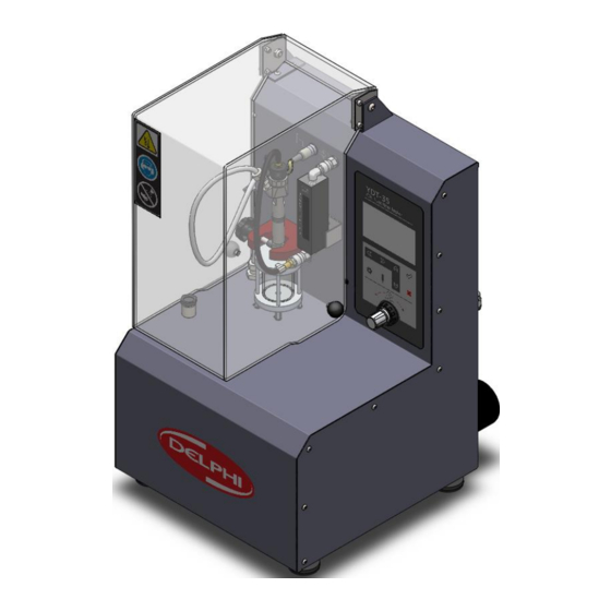
YDT-35 Operating and Servicing Manual 2 Machine Overview Figure 2.1 Overview (front) Tank Filling Cap Back Leak Hose High Pressure Connection Port Injector Driver Cable Spray Chamber Back Leakage Port Backleak (Return) Flow Measurement Injector Clamp Device (optional) Injector Under Test (not included) -
Page 16: Figure 2.2 Overview (Rear)
YDT-35 Operating and Servicing Manual Figure 2.2 Overview (rear) Tank Drain Tap Spray Chamber Filter Fuel Filter Spray Chamber Drain Tap Compressed Air Input Port Fuel Level Indicator Rear Panel (removable for service) Mains electrical inlet and On/Off switch HL066(EN) ISSUE 1, 05/2015 THIS IS AN UNCONTROLLED DOCUMENT downloaded by Lukas Matuska on 16 Feb 2016 Any technical intervention requires certified Hartridge training. -
Page 17: Installation
Figure 3.1 YDT-35 2. Fit the 4 x machine feet to the base of the YDT-35 unit by screwing clockwise (refer to Figure 3.2 ). Ensure the YDT-35 unit is stable and adjust the height of the feet as required. -
Page 18: Electrical Connections
1. Make the electrical connection but do not switch the power on (refer to Figure 3.3). 100-250Vac 50/60Hz Figure 3.3 Mains Electrical Connection 3.3 Air Services connection NOTE: Ensure the air supply connected to the YDT-35 meets the required technical specification. Clean, dry air Minimum pressure 5 bar (72.5 psi) ... -
Page 19: Initial Setup And Power-Up
YDT-35 Operating and Servicing Manual Connect a suitable air supply hose into the push fit air connection on the back of the machine (Figure 3.4, item 1). Do not fill the lower bowl (Figure 3.4, item 2) with lubrication oil; this is a water trap for the air inlet. -
Page 20: Figure 3.5 Tank Filling
YDT-35 Operating and Servicing Manual Figure 3.5 Tank Filling 4. Remove the rubber blanking plug located in the top of the fuel spray chamber (Figure 3.6, item 1). Using a suitable tool, remove the injector O-ring from the top of the fuel spray chamber (Figure 3.6, item 2). -
Page 21: Figure 3.7 Spray Chamber Filling
YDT-35 Operating and Servicing Manual Figure 3.7 Spray Chamber Filling 6. Remove the funnel and refit the injector O-ring into the top of the spray chamber (Figure 3.8). Figure 3.8 Injector O-Ring 7. Backleak (Return) Flow Measurement option - Locate the backleak measurement device into the lower support bracket and push the top of backleak measurement device into the quick-fit port (Figure 3.9, item 1). -
Page 22: Figure 3.9 Backleak (Return) Flow Measurement Option
YDT-35 Operating and Servicing Manual Figure 3.9 Backleak (Return) Flow Measurement Option 8. Ensure that the system pressure regulator on the front of the machine is wound fully anti- clockwise (Figure 3.10). Figure 3.10 Fuel Pressure regulator 9. Close the guard door 10. -
Page 23: Powering Down The Machine
YDT-35 Operating and Servicing Manual Figure 3.11 Mains Electrical Switch 11. On first injector test it will be necessary to run the injector for a minimum of 2 minutes to ensure the hydraulic system is completely purged of air before diagnosing any injectors –... - Page 24 YDT-35 Operating and Servicing Manual This page intentionally left blank HL066(EN) ISSUE 1, 05/2015 THIS IS AN UNCONTROLLED DOCUMENT downloaded by Lukas Matuska on 16 Feb 2016 Any technical intervention requires certified Hartridge training. Contact Hartridge Ltd for details.
-
Page 25: Operation
4.1 Before Testing It is mandatory to clean the injector in an ultrasonic tank/device before installing on the YDT-35. Failure to do so may cause contamination of the fuel system on the YDT-35. Always verify that the Spray Chamber is filled with fluid. -
Page 26: Return Backleak Connection
Return Backleak Connection Refer to Figure 4.1 Push the flexible pipe onto the injector backleak port (item 3) and the YDT-35 backleak port (item 4). The diagram illustrates a typical injector, Injector port positions may vary depending on the manufacturer/type. Confirm the correct location of supply and backleak ports before connecting. -
Page 27: Figure 4.2 Standard Injector Connector (Generic Type)
YDT-35 Operating and Servicing Manual Connector Pin Connector Pin Figure 4.2 Standard Injector Connector (Generic Type) Figure 4.3 Standard Injector Connector (Delphi EU3/4 Type) Figure 4.4 Delphi EU5 Injector Connector Figure 4.5 Bosch CRIN Injector Connector HL066(EN) ISSUE 1, 05/2015 THIS IS AN UNCONTROLLED DOCUMENT downloaded by Lukas Matuska on 16 Feb 2016 Any technical intervention requires certified Hartridge training. -
Page 28: Piezo Injector Polarity
YDT-35 Operating and Servicing Manual 4.2.5 Piezo Injector Polarity WARNING! INVERSE POLARITY MAY DAMAGE PIEZO INJECTORS. MAKE SURE ALL PIEZO INJECTORS USING THE GENERIC TYPE CONNECTOR (FIGURE 4.2) ARE CONNECTED AS ILLUSTRATED BELOW. 4.2.5.1 Bosch Piezo (0445 115 xxx, 0445 116 xxx, 0445 117 xxx) ... -
Page 29: Figure 4.8 Denso Piezo Connector Orientation
YDT-35 Operating and Servicing Manual 4.2.5.3 Denso Piezo (295900-xxxx) Figure 4.8 Denso Piezo Connector Orientation HL066(EN) ISSUE 1, 05/2015 THIS IS AN UNCONTROLLED DOCUMENT downloaded by Lukas Matuska on 16 Feb 2016 Any technical intervention requires certified Hartridge training. Contact Hartridge Ltd for details. -
Page 30: Injector Cable Reference Table
YDT-35 Operating and Servicing Manual 4.2.6 Injector Cable Reference Table Injector Injector Polarity Manual Injector Part Injector Connector Cable Connector Manufacture Type Sensitive Number Standard 0445 110 xxx Coil (fig 4.2) 0445 115 xxx Bosch 0445 116 xxx... -
Page 31: Control Panel
Navigate through the screens and functions using the arrow keys, select via the Start and Stop keys. 4.3.1.1 Home Screen Refer to Figure 4.10 This is the YDT-35 start up screen. The software (sw) and injector database (db) versions are displayed. HL066(EN) ISSUE 1, 05/2015 THIS IS AN UNCONTROLLED DOCUMENT downloaded by Lukas Matuska on 16 Feb 2016 Any technical intervention requires certified Hartridge training. -
Page 32: Figure 4.10 Start Up Screen
YDT-35 Operating and Servicing Manual DELPHI YDT-35 CRi Function Tester sw: 3.0 / db: 1.6 Figure 4.10 Start Up Screen 4.3.1.2 Settings Refer to Figure 4.11 By pressing the “Settings” key on the control panel from the Home Screen, the operator... -
Page 33: Figure 4.11 Settings Screen
YDT-35 Operating and Servicing Manual SETTINGS 1. Tank/Filter TIMERS ► 2. Help Enable 3. Language sw: 3.0 / db: 1.6 Figure 4.11 Settings Screen 4.3.1.3 Injector Selection Refer to Figure 4.12 By pressing the “Injector” button the operator can select a new injector profile from the database. -
Page 34: Tests
YDT-35 Operating and Servicing Manual INJECTOR BRAND SELECTION BOSCH DENSO ► DELPHI Figure 4.13 Injector Selection Screen Use the up/down arrow keys to place the cursor next to the required option. Then press the ‘Start’ key to select the option. -
Page 35: Electrical Test (Ohm / Inductance / Capacitance)
Start key to access it. 4.4.1 Electrical Test (Ohm / Inductance / Capacitance) Refer to Figure 4.15 Depending on the Injector Type and Profile, the YDT-35 will perform a Resistance/Inductance or Capacitance test. Follow the on-screen instructions:- Ohm/Ind/Cap .EJBR-######... -
Page 36: Figure 4.16 'Injector Connected' Symbol
YDT-35 Operating and Servicing Manual WARNING! INVERSE POLARITY MAY DAMAGE PIEZO INJECTORS. MAKE SURE ALL PIEZO INJECTORS USING THE GENERIC TYPE CONNECTOR (FIGURE 4.2) ARE CONNECTED CORRECTLY. When an Injector has been connected, the ‘Injector’ symbol appears at the bottom of the screen (Figure 4.16). -
Page 37: Injector Spray Function Test (Isf)
YDT-35 Operating and Servicing Manual Ohm/Ind/Cap .EJBR-###### 00.43 0.2 – 0.6 60 - 110 START=Test, STOP=Next Figure 4.18 Ohm/Ind/Cap Test Completed Screen 4.4.2 Injector Spray Function Test (ISF) PIEZO INJECTORS CAN OPERATE FOR A MAXIMUM OF 2 MINUTES AT EACH TEST CONDITION. -
Page 38: Figure 4.19 Isf Test Instruction Screen
YDT-35 Operating and Servicing Manual Follow the on-screen instructions:- .EJBR-###### Make all necessary connections to the injector When ready press START. Figure 4.19 ISF Test Instruction Screen Refer to Figure 4.20. When ready, press the Start key. The Spray chamber is illuminated to aid visual checks of the injector spray pattern during the test. -
Page 39: Backleak (Return) Flow Measurement Test (Rfm) - Option
* If YDT-35 Backleak Measurement Unit (8999021) is fitted, observe the flow measurement displayed on the backleak flow indicator. This backleak measurement is purely visual and the operator must determine by observation and comparison with a known ‘good’... -
Page 40: Figure 4.23 Rfm Test Instruction Screen 1
YDT-35 Operating and Servicing Manual Refer to Figure 4.23. Follow the on-screen instructions:- .EJBR-###### If not yet performed, please install the Return Adapter Make all necessary connections to the injector When ready press START. Figure 4.23 RFM Test Instruction Screen 1 When ready, press the START key. -
Page 41: Figure 4.25 Rfm Test Start Screen
YDT-35 Operating and Servicing Manual .EJBR-###### Adjust to MAX Pressure. Press START when ready . . . 180” Bar: 1000 Figure 4.25 RFM Test Start Screen When ready to start the test, press the START key. Refer to Figure 4.26. -
Page 42: Disconnecting & Removing An Injector
The ‘pump’ symbol appears on screen when the return flow test is performed to indicate that the high pressure pump is active, refer to Figure 4.22 When the test has finished, press the Stop key twice to return to the YDT-35 Start up screen. 4.5 Disconnecting & removing an injector 4.5.1 Removing the Injector from the Spray Chamber 1. - Page 43 YDT-35 Operating and Servicing Manual This page intentionally left blank HL066(EN) ISSUE 1, 05/2015 THIS IS AN UNCONTROLLED DOCUMENT downloaded by Lukas Matuska on 16 Feb 2016 Any technical intervention requires certified Hartridge training. Contact Hartridge Ltd for details.
-
Page 44: Troubleshooting
YDT-35 Operating and Servicing Manual 5 Troubleshooting 5.1 Software Error Codes Software Error Description Possible cause/Action Error Code E000 Error present on unit. Reboot the system if no other fault codes are listed on the display. E003 Protective guard cover open Close the cover and restart test. -
Page 45: Troubleshooting Guide
YDT-35 Operating and Servicing Manual 5.2 Troubleshooting Guide Symptom Possible cause/Action Display ‘dead’ Mains supply fuse blown Check the mains inlet fuse, ‘pinch’ the top and bottom Refer to Figure 5.1 tags of the fuse holder and pull to withdraw the fuse. -
Page 46: Figure 5.1 Replacing Fuse
YDT-35 Operating and Servicing Manual Figure 5.1 Replacing Fuse .EJBR-###### ERROR(S) FOUND Press START to Continue Figure 5.2 Error Screen HL066(EN) ISSUE 1, 05/2015 THIS IS AN UNCONTROLLED DOCUMENT downloaded by Lukas Matuska on 16 Feb 2016 Any technical intervention requires certified Hartridge training. Contact Hartridge Ltd for details. -
Page 47: Maintenance
YDT-35 Operating and Servicing Manual 6 Maintenance Prior to any maintenance ensure all services have been isolated. 6.1 Regular Maintenance Frequency Of Checks Operation 20 Hr 3 Mths 12 Mths 36 Mths General Clean/inspection 6.1.1 Check Spray Chamber Fluid 6.1.2... -
Page 48: Check Spray Chamber Fluid
YDT-35 Operating and Servicing Manual 6.1.2 Check spray chamber fluid Every 20 test hours or sooner – 1. Check the spray chamber fluid level. If necessary top up using a syringe or funnel as described in section 3.4. 2. Visually check the fluid for cleanliness. If dirty or dark, change the fluid by opening the spray chamber drain valve on the rear of the machine and emptying the chamber (Figure 6.1). -
Page 49: Spray Chamber Filter Change
YDT-35 Operating and Servicing Manual Figure 6.2 Air Filter Drain 6.1.5 Spray Chamber Filter Change Every 3 months or 50 operating hours, whichever is sooner, the spray chamber filter should be changed to ensure the correct level of cleanliness. If the injectors being tested are excessively dirty a filter check must be carried out more frequently and the filter replaced sooner than the recommended interval. -
Page 50: Fluid Change
YDT-35 Operating and Servicing Manual 6.1.6 Fluid Change When handling calibration fluid, guidelines as stated on the safety data sheet in the appendix must be followed. Every 3 months or 50 operating hours, whichever is sooner, the test fluid should be changed to ensure the correct level of cleanliness. -
Page 51: Backleak (Return) Filter Change
YDT-35 Operating and Servicing Manual The internal Tank/Filter timer will flag up when a change is due. Refer to Figure 6.4 5. Place a suitable container under the drain valve (item 1). Open the drain valve and empty the tank. -
Page 52: Spares
YDT-35 Operating and Servicing Manual 7 Spares Please quote the serial number of the machine when enquiring about spares. 7.1 Accessories supplied with the machine A kit of adaptors (8999000) is supplied with the machine. The kit enables testing of most injectors and comprises:-... -
Page 53: Consumables
8999022 YDT-35 Injector PCB 8999024 YDT-35 Injector Electrical Harness/Cable USB Flash Drive – YDT-35 Manual 8999050 HL066(EN) ISSUE 1, 05/2015 THIS IS AN UNCONTROLLED DOCUMENT downloaded by Lukas Matuska on 16 Feb 2016 Any technical intervention requires certified Hartridge training. Contact Hartridge Ltd for details. -
Page 54: Appendix 1 - Health And Safety Data Sheet
YDT-35 Operating and Servicing Manual 8 Appendix 1 - Health and safety data sheet HEALTH & SAFETY DATA SHEET DATE Pub. No. Information regarding the safe handling & storage of the named product. MAR 97 Applicable to employees and customers. - Page 55 YDT-35 Operating and Servicing Manual This page intentionally left blank HL066(EN) ISSUE 1, 05/2015 THIS IS AN UNCONTROLLED DOCUMENT downloaded by Lukas Matuska on 16 Feb 2016 Any technical intervention requires certified Hartridge training. Contact Hartridge Ltd for details.
- Page 56 The Hartridge Building, Network 421, Radclive Road Buckingham, MK18 4FD United Kingdom Tel: +44(0) 1280 825 659 Fax: +44(0) 1280 825 601 Email: techsupport@hartridge.com https://support.hartridge.com THIS IS AN UNCONTROLLED DOCUMENT downloaded by Lukas Matuska on 16 Feb 2016 Any technical intervention requires certified Hartridge training. Contact Hartridge Ltd for details.
Need help?
Do you have a question about the YDT-35 and is the answer not in the manual?
Questions and answers