Table of Contents
Advertisement
Quick Links
Advertisement
Table of Contents

Summary of Contents for CYP HDBaseT CH-POC1
- Page 1 CH-POC1 HDBaseT Power Inserter Operation Manual Operation Manual...
- Page 3 DISCLAIMERS The information in this manual has been carefully checked and is believed to be accurate. Cypress Technology assumes no responsibility for any infringements of patents or other rights of third parties which may result from its use. Cypress Technology assumes no responsibility for any inaccuracies that may be contained in this document.
- Page 4 SAFETY PRECAUTIONS Please read all instructions before attempting to unpack, install or operate this equipment and before connecting the power supply. Please keep the following in mind as you unpack and install this equipment: • Always follow basic safety precautions to reduce the risk of fire, electrical shock and injury to persons.
-
Page 5: Table Of Contents
CONTENTS 1. Introduction ..........1 2. Applications ........... 1 3. Package Contents ........ 1 4. System Requirements ......1 5. Features ..........1 6. Hardware Description ......2 6.1 Front Panel ........2 6.2 Rear Panel .........3 7. Connection Diagram ......4 8. -
Page 6: Introduction
1. INTRODUCTION The HDBaseT Power Inserter is designed to provide 24V power to a connected PoC-capable HDBaseT Receiver unit for it to operate without power supply. In a simple application of HDBaseT PoC extender set, the Receiver unit can be powered by the connected transmitter unit, over a single run of CAT5e/6/7 cable. -
Page 7: Hardware Description
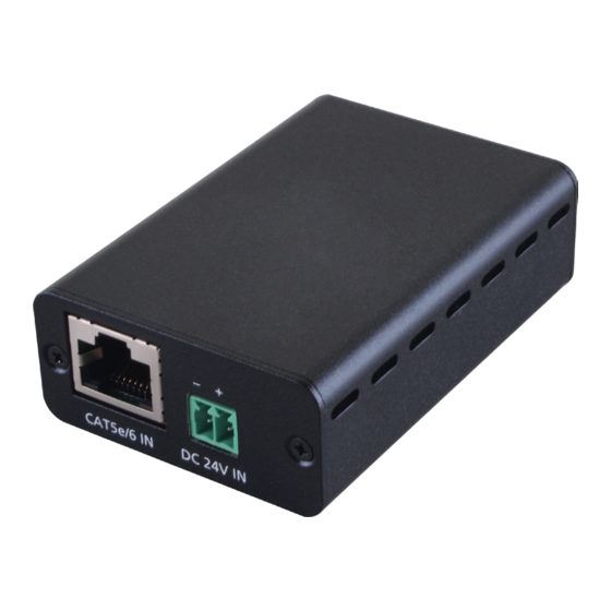
6. HARDWARE DESCRIPTION 6.1 Front Panel DC 24V IN CAT5e/6/7 IN CAT5e/6/7 IN: Connect CAT5e/6/7 cable from a compatible Transmitter. DC 24V IN: Connect 24V DC power supply into the unit with 3.5mm 2-pole Terminal Block connector and connect the adaptor to an AC outlet. -
Page 8: Rear Panel
6.2 Rear Panel POWER DC 24V OUT CAT5e/6/7 OUT POWER LED: This LED will illuminate when the power is connected to power supply DC 24V OUT: Connect this slot to another compatible Receiver for power cascading. CAT5e/6/7 OUT: Connect CAT5e/6/7 cable from a compatible Receiver. -
Page 9: Connection Diagram
7. CONNECTION DIAGRAM Blu-ray or PS3 Player IR2 Blaster Power HDMI IR1 Extender CH-POC1 CAT5e/6/7 IN DC 24V IN CHDBT-1H7CE CAT5e / 6 / 7 OUT HDMI IN HDMI OUT IR IN IR OUT DC 24V EDID SERVICE 1.5m 60° HDMI IR BLASTER IR2 Blaster... -
Page 10: Specifications
8. SPECIFICATIONS Input Ports 1 x RJ-45 1 x DC 24V (3.5mm 2-pole Terminal Block) Output Port 1 x RJ45 1 x DC 24V (3.5mm 2-pole Terminal Block) Power Supply 24V / 2.7A DC (US/EU standards, CE/FCC/ UL certified) ESD Protection Human body model: ±8kV (air-gap discharge) ±4kV (contact discharge) - Page 12 CYPRESS TECHNOLOGY CO., LTD Home page: http://www.cypress.com.tw MPM-CHPOC1...
Need help?
Do you have a question about the HDBaseT CH-POC1 and is the answer not in the manual?
Questions and answers