Table of Contents
Advertisement
Quick Links
Advertisement
Table of Contents

Summary of Contents for Hagerman Audio Labs VACUTRACE
- Page 1 VACUTRACE Vacuum Tube Curve Tracer Made in USA...
-
Page 2: Copyrights And Trademarks
10 years (90 days on tubes). If you discover a defect, Hagerman Audio Labs will, at its option, repair or replace the product at no charge to you provided you return it during the warranty period, transportation charges prepaid to Hagerman Audio Labs. -
Page 3: Specifications
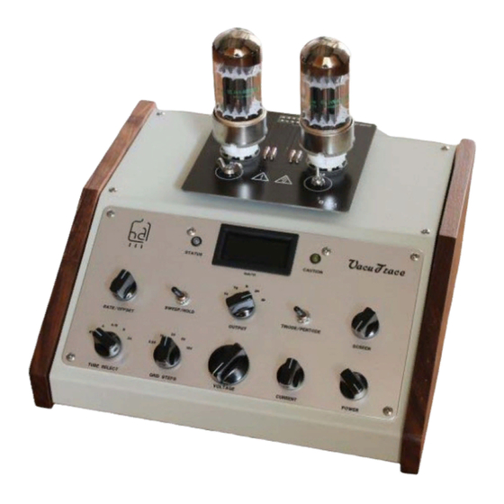
VACUTRACE Vacuum Tube Curve Tracer Description The VacuTrace is a unique piece of laboratory test equipment that converts your analog oscilloscope into a full-features vacuum tube curve tracer. This powerful and flexible combination accurately sweeps the characteristic curves of diodes, triode, tetrodes, and pentodes in real-time. - Page 4 Socket adapter cards are employed to accommodate various tube pinouts. These cards plug onto the connector at the top of VacuTrace and are held in place by four wing nuts. They are built to be rugged and quickly swapped with one another. A socket adapter card must be installed before a vacuum tube can be tested.
-
Page 5: Operation
VACUTRACE Vacuum Tube Curve Tracer Operation Front Panel The controls have been laid out and spaced for easy and intuitive operation. Be sure to select standby mode before changing tubes or socket adapter cards. Control/Indicator Description Tube Select Sets the operating mode and chooses which tube to sweep. -
Page 6: Rear Panel
Status LED indicates the present operating mode or condition. When in standby it is red. During normal operation it is green. If flashing yellow, then VacuTrace is experiencing an overload condition. Caution LED lights up yellow when a voltage greater than 70V is present on the output connector. - Page 7 VACUTRACE Vacuum Tube Curve Tracer Pin # Signal Description PLATE Plate (common to A and B) Cathode (A) GRIDA Grid (A) Switched 6.3V heater power 5V heater center tap, connected to cathode Switched 5V heater power SCREEN Screen (can be switched to plate, common to A and B)
- Page 8 VACUTRACE Vacuum Tube Curve Tracer Generating Curves Setup The most common use of VacuTrace is to sweep the characteristic curves of a vacuum tube. There are two ways to display curves, cathode current vs. grid voltage, and cathode current vs. plate voltage.
- Page 9 VACUTRACE Vacuum Tube Curve Tracer controls as necessary until you have a full set of curves and the tube is running safely within its ratings. Limits Three sweep limit controls are provided to prevent tube damage and allow you to adjust the way you want the curves presented.
-
Page 10: Transfer Function
It is best to start at 100V and work your way up. You may switch modes at any time and set controls to any position in any combination without causing damage to VacuTrace. Transfer Function By switching the Output to gm the oscilloscope display changes to current vs. grid voltage. -
Page 11: Hold Mode
Once the desired operating point is dialed in, switch Output to Ik to read the resulting cathode current in milliamps. Ratios VacuTrace provides dynamic ratio measurements of great value to circuit designers, namely transconductance gain and output conductance. Transconductance (gm) mode measures the ratio of output Ik divided by input Vg given in mA/V. -
Page 12: Taking Measurements
Technology Generating Curves VacuTrace sweeps the characteristic curves of a vacuum tube by applying plate, screen and grid bias voltages and measuring the resulting cathode current. A low value resistor shunts the cathode to ground converting the current into a voltage that is then amplified and sent to the Y channel of the oscilloscope. - Page 13 VACUTRACE Vacuum Tube Curve Tracer In gm (transconductance) mode, a 625Hz modulation is added to the grid output. The dynamic peak-to-peak grid voltage is used as the reference for the LED analog- to-digital converter and the resulting cathode current modulation (just the ac component) is used as the input.
- Page 14 Be careful not to exceed any of the tube’s maximum operating specifications. VacuTrace can deliver a lot of voltage, current and power to a tube. Small signal types such as a 12AX7 are vulnerable to such overdrive.
-
Page 15: Troubleshooting
Faulty tube. Oscilloscope not in XY mode or set up improperly. Heater not warmed up yet. VacuTrace in Stby or Hold modes. Oscilloscope display is XY cables are reversed. backwards. Curves keep VacuTrace is in an overload condition, lower the plate or disappearing. screen voltage or remove fault.
Need help?
Do you have a question about the VACUTRACE and is the answer not in the manual?
Questions and answers