Table of Contents
Advertisement
Advertisement
Table of Contents

Summary of Contents for Rotenso LCAC R32 Series
- Page 1 LCAC R32 SERIES Service Tenji W Jato W manual Nevo W...
-
Page 2: Table Of Contents
LCAC R32 Series LCAC R32 SERIES Service manual Contents SAFETY PRECAUTIONS....................................3 PART 1. GENERAL INFORMATION ................................4 Model Lists ........................................4 External Appearance ....................................5 Nomenclature....................................... 6 PART 2. INDOOR UNITS ....................................7 Tenji - Super Slim Cassette Type ................................7 Nevo - Duct Type ......................................19... -
Page 3: Safety Precautions
LCAC R32 Series SAFETY PRECAUTIONS WARNING Only qualified personnel should install and service the equipment. The installation, starting up, and servicing of heating, ventilating, and air-conditioning equipment can be hazardous and requires specific knowledge and training. Improperly installed, adjusted or altered equipment by an unqualified person could result in death or serious injury. -
Page 4: Part 1. General Information
LCAC R32 Series PART 1. GENERAL INFORMATION 1. MODEL LISTS 1.1 Indoor Units R32 (capacity multiplied by 1000Btu/h) Type Function Tenji - Super slim cassette Cooling and heating Nevo - Duct Cooling and heating Jato - Ceiling-floor Cooling and heating 1.2 Outdoor Units... -
Page 5: External Appearance
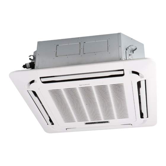
LCAC R32 Series PART 1. GENERAL INFORMATION 2. EXTERNAL APPEARANCE 2.1 Indoor Units Super slim cassette (Tenji Duct (Nevo) Ceiling-Floor (Jato) 2.2 Outdoor Units Single fan outdoor unit Double fan outdoor uni Service manual... -
Page 6: Nomenclature
PART 1. GENERAL INFORMATION 3. NOMENCLATURE 3.1 Indoor Units Revision Indoor unit W series (for R32) Capacity: 5,0kW ~ 16,0kW Rotenso device model name (type): Tenji (Cassette) Jato (Flour-ceiling) Nevo (Duct) 3.2 Outdoor Units Revision Outdoor unit W series (for R32) -
Page 7: Part 2. Indoor Units
LCAC R32 Series PART 2. INDOOR UNITS 1. TENJI - SUPER SLIM CASSETTE TYPE 1.1 FEATURES 1.1.1 Overview • Compact design, super slim body size, less space requiring in installation • Each louver can be separately controlled, more comfort air blowing is possible. - Page 8 LCAC R32 Series PART 2. INDOOR UNITS • Ionizer can be switched on or off by remote controller. When pressing the Clean Air button on the remote controller, Ionizer will work and the indicator light on display board will shine.
- Page 9 LCAC R32 Series PART 2. INDOOR UNITS PART 2. INDOOR UNITS • Due to the improvement of structure, more convenient to repair or replace the draining pump 1.1.6 Terminals for alarm lamp and long-distance on-off controller connection are standard • Reserve terminals for the connection of alarm lamp and long-distance on-off controller, more human control.
- Page 10 LCAC R32 Series PART 2. INDOOR UNITS 1.2 DIMENSIONS 92 92 Fresh air intake 4-install hanger Body Gas side Liquid side Wiring connection port E-parts box Service hole for Test mouth & Test cover draining pump Drain hole 92 92 92 92...
- Page 11 LCAC R32 Series PART 2. INDOOR UNITS 1.3 SERVICE SPACE >1000m m >1000mm 1.4 WIRING DIAGRAMS Service manual...
- Page 12 LCAC R32 Series PART 2. INDOOR UNITS 1.5 AIR VELOCITY DISTRIBUTIONS (REFERENCE DATA) 1.5.1 Units 18-24k a) Cooling: b) Heating: Service manual...
- Page 13 LCAC R32 Series PART 2. INDOOR UNITS 1.5.2 Units 30-42K a) Cooling: b) Heating: Service manual...
- Page 14 LCAC R32 Series PART 2. INDOOR UNITS 1.5.3 Units 48-55K a) Cooling: b) Heating: Service manual...
- Page 15 LCAC R32 Series PART 2. INDOOR UNITS 1.6 ELECTRIC CHARACTERISTICS Indoor Unit POWER SUPPLY Model Voltage T50Wi 220-240 V 198 V 254 V T70Wi 220-240 V 198 V 254 V T100Wi 220-240 V 198 V 254 V T140Wi 220-240 V...
- Page 16 LCAC R32 Series PART 2. INDOOR UNITS 2.8 ACCESSORIES Item Shape Usage category Installation paper board Installation Fittings Soundproof / insulation sheath Tubing & Fittings Out-let pipe sheath Out-let pipe clasp Drainpipe Fittings Drain joint Seal ring Remote controller & Its Frame Remote controller holder Remote controller &...
- Page 17 LCAC R32 Series PART 2. INDOOR UNITS 2.9 THE SPECIFICATION OF POWER Model(Btu/h) 18000~24000 36000 36000 48000~60000 Phase 1-phase 1-phase 1-phase Indoor power Frequency and Voltage 220-240V, 50Hz 220-240V, 50Hz 220-240V, 50Hz Power wiring (mm 3×1.0 3×1.0 3×1.0 Circuit breaker/Fuse (A)
- Page 18 LCAC R32 Series PART 2. INDOOR UNITS 1.10.1 Wiring diagram for T140Wi, T160Wi Service manual...
-
Page 19: Nevo - Duct Type
LCAC R32 Series PART 2. INDOOR UNITS 2. NEVO - DUCT TYPE 2.1 FEATURES 2.1.1 Higher Static Pressure • As a ducted air conditioner with medium static pressure, it has the widest static pressure range. • The maximum static pressure reaches 160 Pa 2.1.2 Slim Design... - Page 20 LCAC R32 Series PART 2. INDOOR UNITS 2.1.4 Flexible Air Intake Way (Bottom side or Rear side) • The frame size of air inlet in rear and bottom is the same. It’s very easy to switch to match different applicatione.
- Page 21 LCAC R32 Series PART 2. INDOOR UNITS 2.1.6 Easy Clean • With a larger window design, once the motor and the blower wheels have been detached, heat exchanger and water receiver tray in behind can be seen very clearly. Dust can be easily removed from the inside by vacuum.
- Page 22 LCAC R32 Series PART 2. INDOOR UNITS 2.2 DIMENSIONS Capacity Unit (kBTU/h) inch 34.65 8.27 26.54 23.62 5.51 27.80 1.97 5.35 30.79 7.48 1.57 36.22 20.00 3.07 5.83 3.46 4.41 1100 1001 1140 inch 43.31 9.80 30.47 27.56 5.51 36.46 1.97 6.89 39.41 8.98...
- Page 23 LCAC R32 Series PART 2. INDOOR UNITS 2.3 SERVICE SPACE Ensure enough space required for installation and maintenance. 2.4 WIRING DIAGRAMS 2.4.1 Wiring diagrams 18K, 24K, 36K, 48K, 55K Service manual...
- Page 24 LCAC R32 Series PART 2. INDOOR UNITS PART 2. INDOOR UNITS 2.5 STATIC PRESSURE 2.5.1 Wiring diagrams N50Wi Air flow rate ( m3/h ) ( no filter ) 2000 1800 1600 1500 1400 1200 1000 External Static Pressure ( pa )...
- Page 25 LCAC R32 Series PART 2. INDOOR UNITS PART 2. INDOOR UNITS 2.5.2 Wiring diagrams N70Wi Air flow rate(m3/h ) ( no filter ) 2400 2200 2000 1800 1600 1400 1200 1000 External Static Pressure ( pa ) 20 25 30...
- Page 26 LCAC R32 Series PART 2. INDOOR UNITS 2.5.3 Wiring diagrams N100Wi Air flow rate(m3/h ) ( no filter ) 3200 3000 2800 2600 2500 2400 2200 2000 1800 1600 1400 1200 1000 External Static Pressure ( pa ) 20 25 30...
- Page 27 LCAC R32 Series PART 2. INDOOR UNITS 2.5.4 Wiring diagrams N140Wi Air flow rate(m3/h ) ( no filter ) 4800 4400 4000 3600 3200 3100 2800 2400 2000 1600 1500 1200 External Static Pressure ( pa ) 20 25 30...
- Page 28 LCAC R32 Series PART 2. INDOOR UNITS PART 2. INDOOR UNITS 2.5.5 Wiring diagrams N160Wi Air flow rate(m3/h ) ( no filter ) 4800 4400 4000 3600 3200 3100 2800 2400 2000 1600 1500 1200 External Static Pressure ( pa )...
- Page 29 LCAC R32 Series PART 2. INDOOR UNITS PART 2. INDOOR UNITS 2.6 ELECTRIC CHARACTERISTICS Indoor Unit POWER SUPPLY Model Voltage N50Wi 220-240 V 198 V 254 V N70Wi 220-240 V 198 V 254 V N100Wi 220-240 V 198 V 254 V...
- Page 30 LCAC R32 Series PART 2. INDOOR UNITS 2.8 ACCESSORIES Item Shape Usage category Soundproof / insulation sheath Tubing & Fittings Drain joint Drainpipe Fittings (for cooling & heating) Seal ring Magnetic ring (twist the electric wires L and N EMC & It’s Fitting (for some models)
- Page 31 LCAC R32 Series PART 2. INDOOR UNITS 2.10 FIELD WIRING 2.10.1 Field wiring N50Wi, N70Wi, N100Wi, N140Wi, 160Wi Service manual...
-
Page 32: Jato - Ceiling & Floor Type
LCAC R32 Series PART 2. INDOOR UNITS 3. JATO - CEILING & FLOOR TYPE 3.1 FEATURES 3.1.1 New design, more modern and elegant appearance 3.1.2 Convenient installation • The ceiling type can be easily installed into a corner of the ceiling even if the ceiling is very narrow •... - Page 33 LCAC R32 Series PART 2. INDOOR UNITS 3.2 DIMENSIONS Wiring connection port Wiring connection port Wiring connection port Wiring connection port Wiring connection port Drain discharge port Drain discharge port Drain discharge port Drain discharge port Drain discharge port Fresh air intake...
- Page 34 LCAC R32 Series PART 2. INDOOR UNITS 3.3 SERVICE SPACE 3.4 WIRING DIAGRAMS 3.4.1 Wiring diagrams J50Wi, J70Wi Service manual...
- Page 35 LCAC R32 Series PART 2. INDOOR UNITS 3.4.2 Wiring diagrams J100Wi, J140Wi, J160Wi 3.5 ELECTRIC CHARACTERISTICS Indoor Unit POWER SUPPLY Model Voltage J50Wi 220-240 V 198 V 254 V J70Wi 220-240 V 198 V 254 V J100Wi 220-240 V 198 V...
- Page 36 LCAC R32 Series PART 2. INDOOR UNITS 3.6 SOUND LEVELS Microphone 1 . 5 m Air outlet side Microphone Ceiling Floor Noise level dB(A) Model Noise Power dB(A) High Medium J50Wi J70Wi J100Wi J140Wi J160Wi Service manual...
- Page 37 LCAC R32 Series PART 2. INDOOR UNITS 3.7 AIR VELOCITY AND TEMPERATURE DISTRIBUTIONS (Reference Data) 3.7.1 Model: 18k, 24k a) Ceiling installation. • Discharge angle 17° Discharge angle 50° • Discharge angle 50° Discharge angle 50° Service manual...
- Page 38 LCAC R32 Series PART 2. INDOOR UNITS b) Floor installation. • Discharge angle 17° • Discharge angle 50° Service manual...
- Page 39 LCAC R32 Series PART 2. INDOOR UNITS 3.7.2 Model: 36k a) Ceiling installation. • Discharge angle 17° Discharge angle 50° • Discharge angle 50° Discharge angle 50° Service manual...
- Page 40 LCAC R32 Series PART 2. INDOOR UNITS b) Floor installation. • Discharge angle 17° Discharge angle 17° Discharge angle 17° Discharge angle 50° • Discharge angle 50° Discharge angle 50° Service manual...
- Page 41 LCAC R32 Series PART 2. INDOOR UNITS 3.7.3 Model: 48k, 55k a) Ceiling installation. • Discharge angle 17° Discharge angle 17° Discharge angle 17° Discharge angle 50° • Discharge angle 50° Discharge angle 50° Service manual...
- Page 42 LCAC R32 Series PART 2. INDOOR UNITS b) Floor installation. • Discharge angle 17° Discharge angle 17° Discharge angle 17° Discharge angle 50° • Discharge angle 50° Discharge angle 50° Service manual...
- Page 43 LCAC R32 Series PART 2. INDOOR UNITS 3.8 ACCESSORIES Item Shape Usage category Remote controller Remote controller & Its holder Remote controller holder (The product you have might not be provided the following accessories) Mounting screw (ST2.9×10-C-H) Alkaline dry batteries (AM4) Owner’s manual...
- Page 44 LCAC R32 Series PART 2. INDOOR UNITS 3.10 FIELD WIRING Service manual...
-
Page 45: Part 3. Outdoor Units
LCAC R32 Series PART 3. OUTDOOR UNITS 1. DIMENSIONS 1.1 Units: 12 - 42k Unit: mm Model (kBtu/h) 1030 Service manual... - Page 46 LCAC R32 Series PART 3. OUTDOOR UNITS 1.2 Units: 48-55k Unit: mm Model (kBtu/h) 48/55 1333 1045 Service manual...
- Page 47 LCAC R32 Series PART 3. OUTDOOR UNITS 2. SERVICE SPACE (Wall or obstacle) More than 30cm Air inlet More than 60cm More than 30cm Maintain channel Air inlet More than 60cm Air outlet More than 200cm 3. WIRING DIAGRAMS 3.1 Wiring diagrams: •...
- Page 48 LCAC R32 Series PART 3. OUTDOOR UNITS 3.2 Wiring diagrams: • T70Wo, N70Wo, J70Wo 3.3 Wiring diagrams: • T140Vo, T160Vo • N140Vo, N160Vo • J 140Vo, J160Vo Service manual...
- Page 49 LCAC R32 Series PART 3. OUTDOOR UNITS 3.4 Wiring diagrams: • T100Wo, N100Wo, J100Wo Service manual...
- Page 50 LCAC R32 Series PART 3. OUTDOOR UNITS 4. PIPING DIAGRAMS 4.1 Wiring diagrams: • T70Wo • N50Wo, N70Wo • J50Wo, J70Wo INDOOR OUTDOOR Electronic CAPILIARY TUBE expansion valve LIQUID SIDE 2-WAY VALVE T3 Condenser temp. sensor HEAT EXCHANGE (EVAPORATOR) HEAT T4 Ambient T1 Room temp.
- Page 51 LCAC R32 Series 4.2 Wiring diagrams: • T100Vo, T140Vo • N100Vo, N140Vo • J100Vo, J140Vo INDOOR OUTDOOR Electronic CAPILIARY TUBE expansion valve LIQUID SIDE 2-WAY VALVE T3 Condenser temp. sensor HEAT EXCHANGE HEAT (EVAPORATOR) T4 Ambient T1 Room temp. EXCHANGE T2 Evaporator temp.
- Page 52 LCAC R32 Series PART 3. OUTDOOR UNITS 5. ELECTRIC CHARACTERISTICS Outdoor Unit POWER SUPPLY Model Voltage N50Wo 220-240 V 198 V 254 V J50Wo T70Wo N70Wo 220-240 V 198 V 254 V J70Wo T100Wo N100Wo 380-415 V 342 V 440 V...
- Page 53 LCAC R32 Series PART 3. OUTDOOR UNITS 7. SOUND LEVELS Outdoor Unit Microphone 1.0m NOTE: H= 0.5 × height of outdoor unit Model Noise Power dB(A) Noise level dB(A) N50Wo J50Wo T70Wo N70Wo J70Wo T100Wo N100Wo J100Wo T140Wo N140Wo J140Wo...
-
Page 54: Part 4. Installation
LCAC R32 Series PART 4. INSTALLATION 1. INSTALLATION PROCEDURE Indoor unit installation Outdoor unit installation location selection location selection Indoor unit installation Outdoor unit installation Refrigerant pipe Refrigerant pipe installation and insulation installation and insulation Drainage pipe installation Drainage pipe installation... -
Page 55: Location Selection
LCAC R32 Series PART 4. INSTALLATION 2. LOCATION SELECTION 2.1 Indoor unit location selection • TThe place shall easily support the indoor unit’s weight. • The place can ensure the indoor unit installation and inspection. • The place can ensure the indoor unit horizontally installed. -
Page 56: Indoor Unit Installation
LCAC R32 Series PART 4. INSTALLATION 3.1 TENJI - SUPER SLIM CASSETTE INDOOR UNIT INSTALLATION 3.1.1 Service space for indoor unit Unit: mm Model (kBtu/h) >235 24~36 >275 48~55 >317 3.1.2 Bolt pitch Service manual... - Page 57 LCAC R32 Series PART 4. INSTALLATION 3.1.3 Install the pendant bolt Select the position of installation hooks according to the hook holes positions showed in upper picture. Drill four holes of Ø12mm, 45~50mm deep at the selected positions on the ceiling. Then embed the expansible hooks (fittings).
- Page 58 LCAC R32 Series PART 4. INSTALLATION Locate the air conditioner firmly by wrenching the nuts after having adjusted the body’s position well. 3.1.5 Install the panel Remove the grille and corner covers. Corner cover Hang the panel to the hooks on the mainbody. If the panel is with auto-lift grille, please watch the ropes lifing the grille, DO NOT make the ropes enwinded or blocked.
- Page 59 LCAC R32 Series PART 4. INSTALLATION Tighten the screws under the panel hooks till the panel closely stick on the ceiling to avoid condensate water Hang the air-in grill to the panel, then connect the lead terminator of the swing motor and that of the control box with corresponding terminators on the body respectively.
-
Page 60: Nevo - Duct Indoor Unit Installation
LCAC R32 Series PART 4. INSTALLATION 3.2 NEVO - DUCT INDOOR UNIT INSTALLATION 3.2.1 Service space for indoor unit 3.2.2 Bolt pitch Unit: mm Size of outline dimension mounted lug Model (kBtu/h) 1140 1400 1240 1240 Service manual... - Page 61 LCAC R32 Series PART 4. INSTALLATION 3.2.3 Hang indoor unit 1. Please refer to the upper data to locate the four positioning screw bolt hole on the ceiling. Be sure to mark the areas where ceiling hook holes will be drilled.
- Page 62 LCAC R32 Series PART 4. INSTALLATION 3.2.4 Duct and accessories installation 1. Install the filter (optional) according to the size of the air inlet. 2. Install the canvas tie-in between the body and the duct. 3. Air inlet and air outlet duct should be apart far enough to avoid air passage short-circuit.
- Page 63 LCAC R32 Series PART 4. INSTALLATION 2. Change the mounting positions of ventilation panel and air return flange. NOTE: All the figures in this manual are for explanation purpose only. They may be slightly different from the air conditioner you purchased.
-
Page 64: Jato - Ceiling & Floor Indoor Unit Installation
LCAC R32 Series PART 4. INSTALLATION 3.3 JATO - CEILING & FLOOR INDOOR UNIT INSTALLATION 3.3.1 Service space for indoor unit 3.3.2 Bolt pitch 1. Ceiling installation Unit: mm Model (kBtu/h) 18/24 1200 36~60 1565 2. Wall-mounted installation Service manual... - Page 65 LCAC R32 Series PART 4. INSTALLATION 3.3.3 Install the pendant bolt 1. Ceiling installation Select the position of installation hooks according to the hook holes positions showed in upper picture. Drill four holes of Ø12mm, 45~50mm deep at the selected positions on the ceiling. Then embed the expansible hooks (fittings).
- Page 66 LCAC R32 Series PART 4. INSTALLATION Locate the hanging arm on the hanging screw bolt. Prepare the mounting bolts on the unit. Put the side panels and grilles back. D. Connecting point of refrigerant pipe (D. gas side) E. Connecting point of refrigerant pipe (E.
-
Page 67: Outdoor Unit Installation (Side Discharge Unit)
LCAC R32 Series PART 4. INSTALLATION 4. OUTDOOR UNIT INSTALLATION (SIDE DISCHARGE UNIT) 4.1 Service space for outdoor unit (Wall or obstacle) More than 30cm Air inlet More than 60cm More than 30cm Maintain channel Air inlet More than 60cm... - Page 68 LCAC R32 Series PART 4. INSTALLATION 5. REFRIGERANT PIPE INSTALLATION 5.1 MAXIMUM PIPE LENGTH AND HEIGHT DROP Considering the allowable pipe length and height drop to decide the installation position. Make sure the distance and height drop between indoor and outdoor unit not exceeded the date in the following table.
- Page 69 LCAC R32 Series PART 4. INSTALLATION 5.2.5 Insulate the copper pipe • Before test operation, the joint parts should not be heat insulated. 5.2.6 Flare the pipe • Insert a flare nut into the pipe before flaring the pipe • According to the following table to flare the pipe...
- Page 70 NOTE: Reduced length of the branching tube is the 0.5m of the equivalent length of the pipe. NOTE: All used branch pipe must be produced by Rotenso, otherwise it causes malfunction. The indoor units should be installed equivalently at the both side of the U type branch pipe.
- Page 71 LCAC R32 Series PART 4. INSTALLATION 5.3.2 Size of joint pipes for outdoor unit (R32) Size of main pipe (mm) Capacity of outdoor unit Gas side Liquid side 1st branching pipe Ø15.9 Ø9.5 CE-FQZHN-01C Ø15.9 Ø9.5 CE-FQZHN-01C Ø15.9 Ø9.5 CE-FQZHN-01C 5.3.4 The branching pipe must be installed horizontally, error angle of it should not large than 10°.
- Page 72 LCAC R32 Series PART 4. INSTALLATION Relationship between water flowrate and capacity of indoor unit Capacity (kBtu) Water flowrate (l/h) According to the above table to calculate the total water flowrate for the confluence pipe selection. For horizontal drainage pipe (The following table is for reference)
- Page 73 LCAC R32 Series PART 4. INSTALLATION 6.2.4 Supporter gap of drainage pipe • In general, the supporter gap of the drainage pipe horizontal pipe and vertical pipe is respectively 1m~1.5m and 1.5m~2.0m. • Each vertical pipe shall be equipped with not less than two hangers.
- Page 74 LCAC R32 Series PART 4. INSTALLATION 6.2.6 Water storage pipe setting • If the indoor unit has high extra static pressure and without water pump to elevate the condensate water, such as high extra static pressure duct unit , the water storage pipe should be set to avoid converse flow or blow water phenomena.
- Page 75 LCAC R32 Series PART 4. INSTALLATION 6.2.8 Blowhole setting • For the concentrated drainage pipe system, there should design a blowhole at the highest point of main pipe to ensure the condensate water discharge smoothly. • The air outlet shall face down to prevent dirt entering pipe.
- Page 76 LCAC R32 Series PART 4. INSTALLATION 2.2 Power on and let the air conditioner operate for cooling. Check operation status of drainage pump, and then connect the plug of water level switch, check the operation sound of water pump and observe whether the water can discharge through the transparent hard pipe at drainage outlet.
- Page 77 LCAC R32 Series PART 4. INSTALLATION 7.3.2 Special vacuum drying The special vacuum drying method shall be adopted when: 1. Finding moisture during flushing refrigerant pipe. 2. Conducting construction on rainy day, because rain water might penetrated into pipeline. 3. Construction period is long, and rain water might penetrated into pipeline.
- Page 78 LCAC R32 Series PART 4. INSTALLATION 9. ENGINEERING OF INSULATION 9.1 INSULATION OF REFRIGERANT PIPE 9.1.1 Operational procedure of refrigerant pipe insulation Cut the suitable pipe insulation (except joint section) flare the pipe piping layout and connection vacuum drying insulate the joint parts 9.1.2 Purpose of refrigerant pipe insulation...
- Page 79 LCAC R32 Series PART 4. INSTALLATION 9.2.3 Insulation material selection for drainage pipe • The insulation material should be flame retardant material, the flame retardancy of the material should be selected according to the local law. • Thickness of insulation layer is usually above 10mm.
- Page 80 LCAC R32 Series PART 4. INSTALLATION • Whether the air flow louver moves normally. • Whether the room temperature is adjusted well. • Whether the indicator lights normally. • Whether the temporary buttons works well. • Whether the drainage is normal.
-
Page 81: Part 5. Electrical Control System
LCAC R32 Series PART 5. ELECTRICAL CONTROL SYSTEM 1. ELECTRICAL CONTROL FUNCTION 1.1 ABBREVIATION T1: Indoor room temperature T2: Middle indoor heat exchanger coil temperature T2B: Indoor heat exchanger exhaust coil temperature T3: Outdoor heat exchanger pipe temperature T4: Outdoor ambient temperature T5: Compressor discharge temperature 1.2 MAIN PROTECTION... - Page 82 LCAC R32 Series PART 5. ELECTRICAL CONTROL SYSTEM controller, or central controller must be used to clear the fan fault and fault count. The fan runs normally for 5 minutes while clearing fault count. 0: No malfunction 1: P0 Overcurrent...
- Page 83 LCAC R32 Series PART 5. ELECTRICAL CONTROL SYSTEM Fan speed is regulated according to T4 and compressor frequency. Frequency linkage area Frequency linkage area: Service manual...
- Page 84 LCAC R32 Series PART 5. ELECTRICAL CONTROL SYSTEM 24~60K 1.3.2.3 Indoor Fan Running Guidelines In cooling mode, the indoor fan runs continuously and You can select the following speeds: high, medium, low, auto or silent. When the compressor is running, The indoor fan is regulated as illustrated as in the following figure: Setting fan T1-Td (°C)(°F)
- Page 85 LCAC R32 Series PART 5. ELECTRICAL CONTROL SYSTEM 1.3.2.4 Evaporator Low Temperature T2 Protection. • T2<0°C, the compressor stops and restarts only when T2≥5°C. • 0°C≤T2<4°C, the compressor frequency is limited and decreases to a lower level • 4°C≤T2<7°C, the compressor maintains its current frequency.
- Page 86 LCAC R32 Series PART 5. ELECTRICAL CONTROL SYSTEM 24~60K: 1.3.3.2 Indoor Fan Running Guidelines In heating mode, indoor fan speed can be set at high, medium, low, or auto fan, and the anti-cold-wind function is preferential. When the compressor is running, The indoor fan is regulated as illustrated as in the following figure:...
- Page 87 LCAC R32 Series PART 5. ELECTRICAL CONTROL SYSTEM 1.3.3.3 Defrosting Control: Conditions for defrosting: • The unit enters the defrosting mode according to the value of T3 and T4 as well as the compressor running time. Defrost Stop Conditions: If any one of the following conditions is satisfied, defrosting ends and the unit returns to heating mode.
- Page 88 LCAC R32 Series PART 5. ELECTRICAL CONTROL SYSTEM preset On Time. • The timer does not change the unit operation mode. If the unit is off now, it does not start up immediately after the “timer off” function is set. When the setting time is reached, the timer LED switches ioff and the unit running mode remains unchanged.
- Page 89 LCAC R32 Series PART 5. ELECTRICAL CONTROL SYSTEM Display Remark Normal display Displays running frequency, running state, or malfunction code Actual data*HP*10 If a capacity demand code is higher than 99, the digital display shows single and Indoor unit capacity demand code double digits.
- Page 90 LCAC R32 Series PART 5. ELECTRICAL CONTROL SYSTEM Display Remark Condenser pipe temperature of #1 indoor If the temperature is lower than 0°C, the digital display shows “0”. If the unit temperature is higher than 70°C, the digital display shows “70. ”...
- Page 91 LCAC R32 Series PART 5. ELECTRICAL CONTROL SYSTEM Shutdown Causes Code Low ambient temperature protection Refrigerant leakage detection Communication malfunction between indoor and outdoor units Communication error between outdoor main chip and compressor driven chip IR341 AC power input voltage protection...
-
Page 92: Part 6. Troubleshooting
LCAC R32 Series PART 6. TROUBLESHOOTING 1. DISPLAY BOARD 1.1 Icon explanation on indoor display board (super slim cassette). 1.2 Icon explanation on indoor display board duct type) PRE-DEF indicator(cooling and heating type) or fan only indicator(cooling only type) Alarm indicator... - Page 93 LCAC R32 Series PART 6. TROUBLESHOOTING 1.4 Display board of ceiling&floor indoor unit 2. INDOOR UNIT MALFUNCTIONS (on); (off ); (flash at 2Hz) Operation Malfunction Error Code Timer Lamp Lamp (flashes) Indoor EEPROM malfunction Communication malfunction between indoor and outdoor units...
- Page 94 LCAC R32 Series PART 6. TROUBLESHOOTING 3. OUTDOOR UNIT MALFUNCTIONS (FOR 24~60K) Display Malfunction or Protection Communication malfunction between indoor and outdoor units Overcurrent protection Ambient temperature sensor (T4) malfunction Outdoor heat-exchanger temperature sensor (T3) malfunction Discharge temperature sensor (T5) malfunction...
- Page 95 LCAC R32 Series PART 6. TROUBLESHOOTING 4. RESOLVING TYPICAL MALFUNCTIONS 4.1 FOR INDOOR UNITS 4.1.1 Temperature Sensor Open or Short Circuit Malfunction conditions If the sampling voltage is lower than 0.06V or higher than 4.94V, the LED will display the failure.
- Page 96 LCAC R32 Series PART 6. TROUBLESHOOTING 4.1.3 Indoor EEPROM Malfunction Malfunction conditions Main PCB chip does not receive feedback from EEPROM chip • Installation mistakes Possible causes • Faulty PCB Power off,then restart the Power off,then restart the unit 2 minutes later.Does a unit 2 minutes later.Does a...
- Page 97 LCAC R32 Series PART 6. TROUBLESHOOTING 4.1.5 Indoor Fan Speed Malfunction When indoor fan speed continues to run at too low a speed (300RPM) for a certain period of time, Malfunction conditions the unit will stop and the LED will display a failure code •...
- Page 98 LCAC R32 Series PART 6. TROUBLESHOOTING DC motor voltage input and output Color Signal Voltage Vs/Vm 200V~380V Black White 13.5-16.5V Yellow 0~6.5V Blue 13.5-16.5V 4.1.6 Refrigerant Leakage Detection Define the evaporator coil temperature T2 of the compressor starts running as Tcool.
- Page 99 LCAC R32 Series PART 6. TROUBLESHOOTING 4.1.7 Outdoor IGBT sensor is faulty Check the connection between temperature Ensure proper connection sensorand PCB. Is it properly wired? Measure the resistance value of the sensor. Is it Replace the sensor within acceptable...
- Page 100 LCAC R32 Series PART 6. TROUBLESHOOTING 4.2 SUPER-SLIM CASSETTES WITH AN UP-DOWN PANEL 4.2.1 Communication Errors between Indoor Unit and Up-Down Panel F7 Displayed F7 Displayed Communication failure between Communication failure between indoor unit and up-down panel indoor unit and up-down panel...
- Page 101 LCAC R32 Series PART 6. TROUBLESHOOTING 4.3 UNITS WITH TWINS FUNCTION (FOR THE SUPER-SLIM CASSETTE & DUCT) 4.3.1 Communication Malfunction between Master Unit and Indoor Uni F3 Displayed Communication failure between master unit and slave unit Check the dial switch settings of Correct the master unit and slave unit.
- Page 102 LCAC R32 Series PART 6. TROUBLESHOOTING 4.4.2 Compressor Speed Malfunction/ Zero Speed Protection / Synchronous Fault Protection LED1(Green) off/LED2 (Red)flash or LED1(Green) flash/LED2 (Red)on Is there at least one LED in the compressor driven chip light? Check the signal wire between the compressor driven chip and the compressor.
- Page 103 LCAC R32 Series PART 6. TROUBLESHOOTING 4.4.4 E1 malfunction • Current loop communication: Indoor unit does not receive feedback from outdoor unit for 110 seconds. This occurs 4 times in a Malfunction conditions row. • Wiring mistakes Possible causes • Faulty indoor or outdoor PCB Power off, then restart the unit 2 minutes later.
- Page 104 LCAC R32 Series PART 6. TROUBLESHOOTING • For 485 Communication Indoor unit does not receive feedback from outdoor unit for 60 seconds OR outdoor unit does not Malfunction conditions receive feedback from indoor unit for 120 seconds. • Wiring mistakes Possible causes •...
- Page 105 LCAC R32 Series PART 6. TROUBLESHOOTING F0 displayed Current protection of compressor Was the protection activated in standby? Is the power voltage is Restart the unit when the power normal? supply returns to normal Is outdoor terminal voltage Is the power wiring...
- Page 106 LCAC R32 Series PART 6. TROUBLESHOOTING 4.4.6 F1, F2, F3 Malfunction Error displayed Judge 1: Outdoor condenser temp. sensor (T3) is malfunctioning Is the wiring of the condenser temp. Reconnect the condenser sensor (T3) not connected properly? temp. sensor (T3) Is the resistance of condenser temp.
- Page 107 LCAC R32 Series PART 6. TROUBLESHOOTING 4.4.7 F4 Malfunction Malfunction conditions Main PCB chip does not receive feedback from EEPROM chip • Installation mistakes Possible causes • Faulty PCB F4-Display Outdoor EEPROM malfunction Power off, then restart the unit 2 minutes later. Does a...
- Page 108 LCAC R32 Series PART 6. TROUBLESHOOTING First, test the resistance between every two ports of U, V, the W of the IPM and P, N. If any of the results is 0 or close to 0, the IPM is defective. If not, follow the following procedure:...
- Page 109 LCAC R32 Series PART 6. TROUBLESHOOTING 4.4.10 P1 malfunction Malfunction conditions An abnormal voltage rise or drop is detected by checking the specified voltage detection circuit. • Abnormal power supply • Wiring mistake Possible causes • Faulty bridge rectifier • Faulty IPM board...
- Page 110 LCAC R32 Series PART 6. TROUBLESHOOTING 4.4.11 P4 Malfunction The troubleshooting is same as the “IPM module protection” 4.4.12 J0 Malfunction When evaporator coil temperature is more than 60°C, the unit stops. It starts again only when the Malfunction conditions evaporator coil temperature is less than 54°C...
- Page 111 LCAC R32 Series PART 6. TROUBLESHOOTING 4.4.13 J1 Malfunction When the outdoor pipe temperature is more than 65°C, the unit stops. It starts again only when the Malfunction conditions outdoor pipe temperature is less than 52°C. • Faulty condenser temperature sensor Possible causes •...
- Page 112 LCAC R32 Series PART 6. TROUBLESHOOTING 4.4.14 J2 Malfunction When the compressor discharge temperature (T5) is more than 115°C for 10 seconds, the Malfunction conditions compressor will stop and not restart until T5 is less than 90°C. • Refrigerant leakage •...
- Page 113 LCAC R32 Series PART 6. TROUBLESHOOTING 4.4.15 J3 Malfunction When the voltage signal that IPM send to compressor drive chip is abnormal, the display LED will Malfunction conditions show “P6” and AC will turn off. • Wiring mistake • Faulty IPM board Possible causes •...
- Page 114 LCAC R32 Series PART 6. TROUBLESHOOTING 4.4.16 J4 Malfunction J4 displayed Communication error between outdoor main chip and compressor driven chip Is there at least one LED in the compressor driven chip light? Check the signal wire between the Compressor driven chip and the...
- Page 115 LCAC R32 Series PART 6. TROUBLESHOOTING 4.4.17 J5 Malfunction Malfunction conditions If the sampling voltage is not 5V, the LED displays a failure code. • Wiring mistakes • Faulty overload protector Possible causes • System blockages • Faulty outdoor PCB...
- Page 116 LCAC R32 Series PART 6. TROUBLESHOOTING 4.4.18 P6/J6 Malfunction Malfunction conditions If the sampling voltage is not 5V, the LED displays a failure code. • Wiring mistake • Faulty over load protector Possible causes • System blockages • Faulty outdoor PCB...
- Page 117 LCAC R32 Series PART 6. TROUBLESHOOTING 4.4.19 J8 malfunction Malfunction conditions An abnormal voltage rise or drop is detected by checking the specified voltage detection circuit. • Abnormal power supply • Wiring mistake Possible causes • Faulty bridge rectifier • Faulty IPM board...
-
Page 118: Part 7. Capacity Tables
LCAC R32 Series PART 7. CAPACITY TABLES 1. TENJI - SUPER SLIM CASSETTE 1.1 Capacity tables for 18K a) Cooling TC: Total Capacity; SHC: Sensible Heat Capacity; PI: Power Input Outdoor temperature (DB, °C) Indoor °C °C 5,44 4,24 1,25... - Page 119 LCAC R32 Series PART 7. CAPACITY TABLES b) Heating TC: Total Capacity; PI: Power Input Outdoor temperature (DB, °C) Indoor °C 4,16 2,21 4,94 2,55 5,53 2,51 5,89 2,49 6,58 2,54 7,14 2,59 7,85 1,99 7,61 1,85 7,30 1,79 4,10...
- Page 120 LCAC R32 Series PART 7. CAPACITY TABLES 1.4 Capacity tables for 48K a) Cooling TC: Total Capacity; SHC: Sensible Heat Capacity; PI: Power Input Outdoor temperature (DB, °C) Indoor °C °C 14,36 11,20 3,90 13,74 11,00 4,25 13,13 10,76 4,60...
- Page 121 LCAC R32 Series PART 7. CAPACITY TABLES b) Heating TC: Total Capacity; PI: Power Input Outdoor temperature (DB, °C) Indoor °C 9,56 4,83 10,97 5,09 13,31 5,50 13,50 5,62 14,62 6,03 16,12 5,80 18,75 5,85 18,18 5,45 17,43 5,27 9,42...
- Page 122 LCAC R32 Series PART 7. CAPACITY TABLES 2.2 Capacity tables for 24K a) Cooling TC: Total Capacity; SHC: Sensible Heat Capacity; PI: Power Input Outdoor temperature (DB, °C) Indoor °C °C 7,18 5,60 1,67 6,87 5,50 1,81 6,56 5,38 1,96...
- Page 123 LCAC R32 Series PART 7. CAPACITY TABLES b) Heating TC: Total Capacity; PI: Power Input Outdoor temperature (DB, °C) Indoor °C 6,71 3,90 8,15 4,07 8,97 4,04 9,47 4,02 9,94 3,90 10,33 3,81 11,47 2,91 11,13 2,71 10,67 2,62 6,61...
- Page 124 LCAC R32 Series PART 7. CAPACITY TABLES 2.5 Capacity tables for 55K a) Cooling TC: Total Capacity; SHC: Sensible Heat Capacity; PI: Power Input Outdoor temperature (DB, °C) Indoor °C °C 15,80 12,32 4,12 15,12 12,10 4,49 14,44 11,84 4,86...
- Page 125 LCAC R32 Series PART 7. CAPACITY TABLES b) Heating TC: Total Capacity; PI: Power Input Outdoor temperature (DB, °C) Indoor °C 2,64 1,34 3,38 1,47 3,53 1,49 3,61 1,47 3,84 1,40 4,02 1,35 5,74 1,46 5,56 1,35 5,34 1,31 2,60...
- Page 126 LCAC R32 Series PART 7. CAPACITY TABLES 3.3 Capacity tables for 36K a) Cooling TC: Total Capacity; SHC: Sensible Heat Capacity; PI: Power Input Outdoor temperature (DB, °C) Indoor °C °C 10,77 8,40 3,00 10,31 8,25 3,27 9,84 8,07 3,54...
- Page 127 LCAC R32 Series PART 7. CAPACITY TABLES b) Heating TC: Total Capacity; PI: Power Input Outdoor temperature (DB, °C) Indoor °C 8,46 4,80 9,70 5,00 11,10 5,09 11,94 5,14 13,46 5,36 14,68 5,54 16,58 4,90 16,09 4,56 15,42 4,41 8,33...
-
Page 128: Part 8. Appendix
LCAC R32 Series PART 8. APPENDIX 1. TEMPERATURE SENSOR RESISTANCE VALUE TABLE (°C - K) °C K Ohm °C K Ohm °C K Ohm °C K Ohm 115.266 12.6431 2.35774 0.62973 108.146 12.0561 2.27249 0.61148 101.517 11.5000 2.19073 0.59386 96.3423 10.9731... - Page 129 LCAC R32 Series PART 8. APPENDIX 2. DISCHARGE TEMPERATURE SENSOR TABLE (°C - K) °C K Ohm °C K Ohm °C K Ohm °C K Ohm 542.7 68.66 13.59 3.702 511.9 65.62 13.11 3.595 62.73 12.65 3.492 455.9 59.98 12.21 3.392...
- Page 130 LCAC R32 Series PART8. APPENDIX 3. NORMAL VOLTAGE OF P AND N 208-240V (1-phase, 3-phase) 380-415V (3-phase) In standby: Around 310 VDC Around 530 VDC In operation: With passive PFC module With partial active PFC module With fully active PFC module >200VDC...
- Page 131 LCAC R32 Series NOTES ............................................................................................................................................................................................................................................................................................................................................................................................................................................................................................................................................................................................................................................................................................................................................................................................................................................................................................................................................................................................................................................................................................................................................................................................................................................................................................................................................................................................Service manual...
- Page 132 Installer stamp...
Need help?
Do you have a question about the LCAC R32 Series and is the answer not in the manual?
Questions and answers