
Subscribe to Our Youtube Channel
Related Manuals for SRS Labs DC205

Summary of Contents for SRS Labs DC205
- Page 1 Operation and Service Manual Precision DC Voltage Source DC205 Stanford Research Systems Revision 1.15 October 25, 2019...
- Page 2 Copyright c Stanford Research Systems, Inc., 2019. All rights reserved. Stanford Research Systems, Inc. 1290–D Reamwood Avenue Sunnyvale, CA 94089 USA Phone: (408) 744-9040 Fax: (408) 744-9049 www.thinkSRS.com e-mail: info@thinkSRS.com Printed in U.S.A. Document number 9-01745-903 DC205 Precision DC Voltage Source...
-
Page 3: Table Of Contents
Contents General Information Safety and Preparation for Use ....Symbols ......Notation . - Page 4 DC source status (DCCR DCEV) ..4 – 24 5 Field Calibration 5 – 1 Introduction to field calibration ... . . 5 – 2 DC205 Precision DC Voltage Source...
- Page 5 A.2 ac voltage selector ..... A – 1 A.3 Fuse installation ..... . A – 3 DC205 Precision DC Voltage Source...
- Page 6 Contents DC205 Precision DC Voltage Source...
-
Page 7: General Information
AC line voltage The DC205 Precision DC Voltage Source operates from a 100 V, 120 V, 220 V–230 V, or 240 V nominal ac power source having a line fre- quency of 50 Hz or 60 Hz. Before connecting the power cord to a... -
Page 8: Symbols
Symbols you may Find on SRS Products Symbol Description Alternating current Caution - risk of electric shock Frame or chassis terminal Caution - refer to accompanying documents Earth (ground) terminal Battery Fuse On (supply) Off (supply) DC205 Precision DC Voltage Source... -
Page 9: Notation
Literal text other than command names is set as OFF Remote command examples will all be set in monospaced font. In these examples, data sent by the host computer to the DC205 are set as straight teletype font, while responses received by the host computer from the DC205 are set as slanted teletype font. -
Page 10: Specifications
100 V preliminary Noise and drift Range Temperature Noise coe cient (typical) 0 C – 40 C (0.1 – 10) Hz 10 Hz – 100 kHz ( ppm setting V) C Vrms 10 V 100 V DC205 Precision DC Voltage Source... - Page 11 0 C to 40 C, non-condensing Power 20 W, 100 120 220 240 VAC, 50 60 Hz Dimensions 8 3 W 3 5 H 13 D Weight 10 lbs Fuse two (2) metric size 5 20 mm DC205 Precision DC Voltage Source...
- Page 12 General Information DC205 Precision DC Voltage Source...
-
Page 13: Getting Started
1 Getting Started This chapter provides step-by-step instruction to get started quickly with the DC205 Precision DC Voltage Source. Refer to chapter 2 for a more complete introduction to the DC205. In This Chapter How to use this manual ....1 – 2 Preliminaries . -
Page 14: How To Use This Manual
Those who want to begin with an overview to the functional layout of the instrument should turn to Chapter 2. Users who prefer to jump in and begin using the DC205 first should continue with this Chapter, where a series of step-by-step procedures are given to verify the basic performance of the instrument. - Page 15 2. Plug the AC line cord into the rear-panel power entry module, and then into a grounded wall outlet. 3. Using banana-plug test leads, connect the DC205 OUTPUT terminals (HI and LO) to the voltmeter input terminals (HI and LO). Turn on the voltmeter and set it to DCV, Autorange.
-
Page 16: User Interface
3. Push the knob in, then release. least significant digit should begin to blink. Now slowly turn the knob clockwise. The DC205 will click, and the least significant digit (tens of micro- volts) will begin incrementing. Continue turning the knob until the display shows 4. -
Page 17: Instrument Settings
The SENSE setting selects 2-wire or 4-wire (remote sensing) for the voltage source circuitry. 1. If the OUTPUT On indicator is lit, disable the DC205 OUTPUT by pressing the [On O ] button. 2. Connect a pair of banana test leads from the red and black SENSE terminals on the DC205 to the input HI, LOW terminals on the multimeter. - Page 18 1.000 000 V. 7. Use the SELECT ADJUST buttons or the knob to adjust the DC205 until the multimeter displays exactly 1.000 000 V, with a minimum of 100 V resolution. 8. Attach a 50 BNC terminator to the banana-to-BNC adaptor.
-
Page 19: Isolation
1.0000 V appears on the multimeter. 5. Connect another banana test lead from the green chassis ground terminal on the DC205 front panel to the red HI banana lead at the DC205. Notice that the multimeter still displays 1.0000 V, even though the HI terminal is now connected to chassis ground. -
Page 20: Scanning
1 – 8 Getting Started 1.5.3 Scanning In addition to generating a stable DC voltage, the DC205 is also able to create linear sweeps of the output voltage. This example will demonstrate one such sweep. 1. If the OUTPUT On indicator is lit, disable it by pressing the [On O ] button. - Page 21 [Enter Start] button to start the scan. 13. While the scan is running, notice that the multimeter and the DC205 display are both smoothly sweeping from 0.1 V to 0.8 V. After 10 seconds, the scan should end and the output voltage settles at 0.8 V.
-
Page 22: Interlock
100 V, capable of causing injury or death. Figure 1.1: The DC205 rear panel, shown with an interlock defeat plug. For safety, the 100 V range can only be enabled when the interlock signal is closed. To close the interlock, a low impedance circuit must be established between pins 1 and 2 of the rear-panel INTERLOCK header. -
Page 23: Operation
2 Operation This chapter provides a basic overview of the DC205 Precision DC Voltage Source. In This Chapter Navigating the front panel ....2 – 2 2.1.1... -
Page 24: Navigating The Front Panel
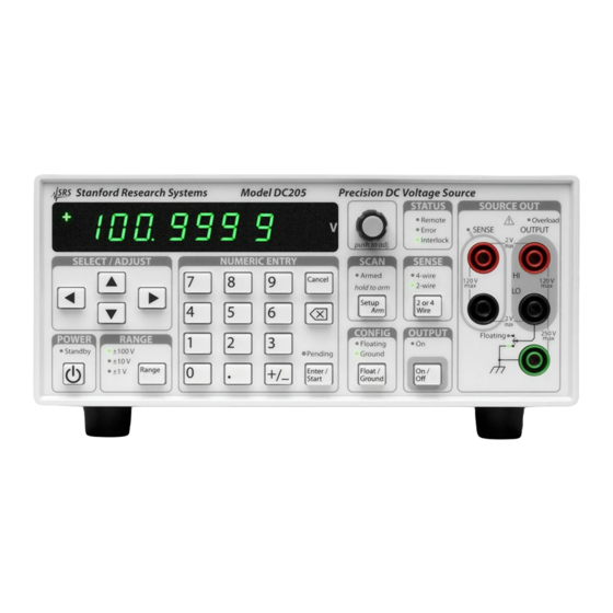
Figure 2.1: The DC205 front panel. 2.1.1 Power When the DC205 is connected to an AC power source, the power supply will initially be in standby mode, indicated by the Standby indicator in the POWER section. To turn the DC205 on, press and hold the [ ] button until Standby is no longer lit, and the rest of the display comes on. -
Page 25: Range
Pressing and holding the [ ] button while turning on power will place the instrument in Field Calibration mode. You can read more about field calibration of the DC205 in chapter 5 (page 5 – 1 ). DC205 Precision DC Voltage Source... - Page 26 2.1.1.4 Baud rate Pressing and holding the [Setup Arm] button while turning on power will cause the DC205 baud rate to be displayed on the numeric dis- play. Use the [ ] and [ ] buttons to select between 9600, 19200, 38400, 57600, and 115200 baud.
- Page 27 2.1.3 Select / Adjust The cluster of arrow buttons in the SELECT ADJUST block provides a flexible interface to controlling the voltage setting of the DC205. When the display is in the “display-idle” state, the voltage setting will be displayed and no digit will be blinking. Pressing any of the four arrow buttons once will cause the most-recently selected digit to begin blinking, indicating the focus for editing the setting.
-
Page 28: Numeric Entry
2.1.4 Numeric Entry The numeric entry keypad is used to directly enter voltage settings to the DC205. Values are implicitly positive unless the [ ] button is pressed, which will toggle the sign between positive and negative. -
Page 29: Sense
2.1.5 Sense The [2 or 4 Wire] button in the SENSE block controls whether the DC205 uses local or remote feedback for controlling the voltage at the load. Pressing [2 or 4 Wire] toggles between 2-wire and 4-wire. This can be performed at any time, regardless of the state of the output. -
Page 30: Scan
Once armed, scans can also be started by applying a falling edge to the TRIG In BNC connector on the DC205 rear panel, or the remote *TRG command. DC205 Precision DC Voltage Source... -
Page 31: Output
DC205. The Remote indicator illuminates whenever remote commands are received by the DC205 from any of the three remote interfaces. The indicator is not persistent—it will light briefly each time remote com- mand characterss are received. -
Page 32: Source Out
(page viii). When 4-wire mode is selected for SENSE, the red and black terminals under the SENSE label are used for four-wire (remote) sensing of the output voltage. When these input terminals are active, the SENSE DC205 Precision DC Voltage Source... -
Page 33: Scanning
Voltage scanning was briefly introduced in the previous chapter, under section 1.5.3. Scanning allows the user to setup and execute linear sweeps of the output voltage of the DC205. 2.2.1 Overview of scanning Scans are implemented by dividing the time interval of a scan into... -
Page 34: Arming Scans
Δt Armed Tri ered Figure 2.3: The DC205 scan modes, shown schematically. Time flows hor- izontally from left to right. All four examples are shown start- ing in the “Armed” state, with the scan beginning at the point marked “Triggered.” The scan duration t is indicated near the bottom, and is common for all plots. -
Page 35: Triggering Scans
Connect the BUSY Out signal from the “master” DC205 to the “slave” unit(s) TRIG In connectors. Config- ure each DC205 for the desired scan parameters, and then arm each of the units. To begin the syncronized scan, trigger the scan from the master unit using any of the 3 methods listed in section 2.2.4. -
Page 36: Ending Or Cancelling Scans
SCAA IDLE (see section 4.4.6). When a scan is stopped in this way, the output voltage is left at the most-recent setting of the scan, with the output still on. See Figure 2.4. DC205 Precision DC Voltage Source... -
Page 37: Error Messages
2.3.1.2 Configuration lost If the memory recording the last configuration of the DC205 is deter- mined to be corrupted upon power-up, the message is displayed. This message may be cleared by pressing any button, after which the instrument will begin operating from the default configuration (as though *RTS had run). -
Page 38: Field Calibration
2.3.4 Interlock If the DC205 is operating on the 100 V range with the output on, and the safety interlock opens, then the message will be displayed. This message will persist until the user presses [Cancel] or another button, or sends any remote commanding data. -
Page 39: Unexpected Resets
2 – 17 2.3.5 Unexpected resets A number of internal protections may cause the DC205 to generate an internal reset in response to a hardware failure. If this occurs, one of the following messages is displayed to indicate the failure. The message will persist until the user presses [Cancel], after which the instrument will (attempt to) resume normal operation. - Page 40 2.3.5.12 Unknown indicates a reset of unknown origin. 2.3.5.13 Lockup indicates a cpu core lockup failure. 2.3.5.14 Peripheral failure indicates a cpu peripheral failed to acknowledge stop mode. DC205 Precision DC Voltage Source...
-
Page 41: Architecture
3 Architecture This chapter describes the architecture and theory of operation of the DC205 Precision DC Voltage Source. In This Chapter Overview ......3 – 2 Voltage reference . -
Page 42: Overview
These elements are: 1. A low-noise, stable voltage reference 2. A high-resolution digital-to-analog converter 3. A set of low-noise, low-distortion amplifiers A simplified block diagram of the DC205 is shown in Figure 3.1. ±100 V Power Interlock... -
Page 43: Voltage Reference
DC205, the important aspect of the voltage reference is not its initial accuracy but rather its stability over time. The accuracy of the DC205 is estab- lished at factory calibration time by reference to a NIST-tracable high precision voltmeter. -
Page 44: Amplifiers
3 – 4 Architecture 3.4 Amplifiers Two distinct output amplifiers are incorporated in the DC205 to ac- comodate the three output voltage ranges. 3.4.1 High-range amplifier The highest output range, 100 V, has a dedicated output circuit powered by 120 V supply rails. This entire subsystem, including the power to the high-range amplifier, is enabled only when the... - Page 45 3.5 Remote sensing 3 – 5 line. These resistors ensure that when the DC205 is operating in 4- wire mode but the sense leads are not connected, there remains some local feedback to keep the output regulated. Additionally, there are two antiparallel chains of PN diodes between the sense leads and their corresponding output leads.
- Page 46 3 – 6 Architecture DC205 Precision DC Voltage Source...
-
Page 47: Remote Operation
4 Remote Operation This chapter describes operating the DC205 Precision DC Voltage Source over the remote interfaces. In This Chapter Index of commands ....4 – 2 Alphabetic list of commands . -
Page 48: Index Of Commands
4 – 15 Token Mode TERM(?) z 4 – 15 Response Termination *OPC(?) 4 – 15 Operation Complete COPC 4 – 16 Cancel Pending *OPC Flag BAUD(?) z 4 – 16 Serial Baud Rate *RST 4 – 17 Reset DC205 Precision DC Voltage Source... - Page 49 DCPT(?) [i,] j 4 – 20 DC Source Positive-Transition DCNT(?) [i,] j 4 – 20 DC Source Negative-Transition DCEV? [i] 4 – 21 DC Source Event DCEN(?) [i,] j 4 – 21 DC Source Event Enable DC205 Precision DC Voltage Source...
-
Page 50: Alphabetic List Of Commands
4 – 18 Interlock ISOL(?) z 4 – 9 Output isolation KCLK(?) z 4 – 14 Key Clicks LCME? 4 – 20 Last command error LEXE? 4 – 19 Last Execution Error OVLD? 4 – 18 Overload DC205 Precision DC Voltage Source... - Page 51 4 – 12 Scan Time SENS(?) z 4 – 9 Remote Sensing SOUT(?) z 4 – 9 Output TERM(?) z 4 – 15 Response Termination TOKN(?) z 4 – 15 Token Mode VOLT(?) f 4 – 10 DC Voltage DC205 Precision DC Voltage Source...
-
Page 52: Introduction
4 – 6 Remote Operation 4.3 Introduction Remote operation of the DC205 is through a simple command lan- guage documented in this chapter. Both set and query forms of most commands are supported, allowing the user complete control of the voltage source from a remote computer through USB or RS-232, or through the optical fiber and the SX199 interface to GPIB, RS-232, or... -
Page 53: Commands
4-wire, the following two commands are equivalent: SENS FOURWIRE —or— SENS 1 For queries that return token values, the return format (keyword or integer) is specified with the TOKN command. DC205 Precision DC Voltage Source... -
Page 54: Notation
In these examples, all data sent by the host computer to the DC205 are set as straight teletype font, while responses received by the host computer from the DC205 are set as slanted teletype font. The usage examples vary with respect to set query, optional param- eters, and token formats. -
Page 55: Configuration Commands
(RANGE1 0, RANGE10 1, RANGE100 2) . The RNGE command is equivalent to pressing the [Range] button. RNGE sets the output range of the DC205 to one of the three range settings: 1 V, 10 V, or 100 V. -
Page 56: Setting Commands
Note also that VOLT? queries always respond with the voltage setting of the instrument—no actual measurement of output voltage is ever performed by the DC205. The VOLT command is equivalent to the front panel numeric entry keypad. Example: VOLT 1.25e-3; VOLT? 0.001250 DC205 Precision DC Voltage Source... -
Page 57: Scan Commands
4.4 Commands 4 – 11 4.4.6 Scan commands The DC205 can perform linear voltage scans, either as a single-shot or indefinitely repeating pattern. The following commands provide the remote interface to this capability. SCAR(?) z Scan Range Set (query) the scan range to z (RANGE1 0, RANGE10 1, RANGE100 2) . - Page 58 SCAE to SCAB, at the conclusion of each cycle. When SCAC ONCE is set, the output voltage remains at SCAE at the conclusion of the scan. DC205 Precision DC Voltage Source...
- Page 59 (IDLE 0, ARMED 1, or SCANNING 2). Setting SCAA ARMED will arm the scan. In order to successfully arm the scan, the DC205 must already have the output enabled. Also, the present range setting (RNGE) must match the programmed scan range (SCAR), and the beginning and ending voltages of the scan (SCAB and SCAE) must not be equal.
-
Page 60: Setup Commands
(see section 2.1.1.6 on page 2 – 4 ). 4.4.8 Interface commands *IDN? Identify Query the DC205 identification string. The response is formatted as: Stanford Research Systems,DC205,s/n********,ver#.## where ******** is the 8-digit serial number, and #.## is the firmware revision level. - Page 61 LF character, while queries received on the ethernet interface shall generate response messages terminated by the CR and LF characters. TERM settings not are saved when the DC205 is powered o . They are not a ected by *RST. Example:...
- Page 62 10 s, turns the output on, arms the scan, and then triggers the scan. The final *OPC? query requests the DC205 to reply 1 when the scan is finished. The final response (1) does not appear until the scan is finished, 10 s after the scan starts.
- Page 63 Note that the RS-232 baud rate is una ected by *RST. The same default configuration can be set by performing a power-on reset of the DC205(see section 2.1.1.1 on page 2 – 3 ). Note, however, that the front-panel power-on reset will also reset the RS-232 baud rate to 9600.
-
Page 64: Status Commands
Set (query) the Service Request Enable register [bit i] to j . Example: *SRE 0,1 *ESR? [i] Standard event status Reads the Standard Event Status Register [bit i]. Upon executing *ESR?, the returned bit(s) of the ESR register are cleared. Example: *ESR? DC205 Precision DC Voltage Source... - Page 65 Example: RNGE 0; VOLT 3.1; LEXE?; LEXE? The error (1, “Illegal value,”) is because the parameter value (3.1) is too large for VOLT on the 1 V range. The second read of LEXE? returns 0. DC205 Precision DC Voltage Source...
- Page 66 Set (query) the DC Source Positive Transition Register [bit i] to j . Example: DCPT 1,1 DCNT(?) [i,] j DC Source Negative-Transition Set (query) the DC Source Negative Transition Register [bit i] to j . Example: DCNT? DC205 Precision DC Voltage Source...
- Page 67 Upon executing an DCEV? query, the returned bit(s) of the DCEV register are cleared. Example: DCEV? DC Source Event Enable DCEN(?) [i,] j Set (query) the DC Source Status Enable Register [bit i] to j . Example: DCEN 1,1 DC205 Precision DC Voltage Source...
-
Page 68: Dc Source Status (Dccr Dcev)
Interlock OVLD DCCR DCPT DCNT DCEV DCEN Figure 4.1: Status Model for the DC205 Precision DC Voltage Source There are five categories of registers in the status model of the voltage source: Condition Registers : These read-only registers correspond to the real-time condi- tion of some underlying physical property being monitored. - Page 69 At power-on, all status registers are cleared. 4.5.1 Status byte (SB) The Status Byte is the top-level summary of the DC205 status model. When enabled by the Service Request Enable register, a bit set in the Status Byte causes the MSS (Master Summary Status) bit to be set.
- Page 70 *ESE(?) command. At power-on, this register is cleared. 4.5.4 DC source status (DCCR/DCEV) The DC source status is monitored by a real-time condition register (DCCR), a pair of transition selection registers, and the latching event register. DC205 Precision DC Voltage Source...
- Page 71 4.5 Status model 4 – 25 4.5.4.1 DC source condition (DCCR) The DC Source Condition Register consists of 2 condition flags that reflect the real-time condition of the DC205. Reading the DCCR has no e ect on any values. Weight Flag...
- Page 72 4.5.4.4 DC source status enable (DCSE) This is an 8-bit wide register that masks the DCEV register. The logical OR of the bitwise AND of DCEV and DCEN produces the DCSB message in the Status Byte register (SB). DC205 Precision DC Voltage Source...
-
Page 73: Field Calibration
5 Field Calibration This chapter provides instructios for calibrating the DC205 Precision DC Voltage Source in the field. In This Chapter Introduction to field calibration ... . 5 – 2 Calibration method . -
Page 74: Introduction To Field Calibration
As a result, it is typically possible to restore the DC205 to its 24-hour accuracy level by applying a more limited calibration procedure, correcting gain and o set but leaving the small non-linear corrections unchanged from their factory settings. -
Page 75: Equipment Needed
6.3. Be sure to label these measurements “pre-calibration” to avoid confusion with the post calibration verification. 4. Turn o power to the DC205 by pressing the front panel [ ] button. While holding the [ ] button depressed, press the [ ] button again to turn on into field calibration mode. - Page 76 (such as a 10 mV or 100 mV full-scale range). For consistent results, a single fixed range should be used for all 3 measurements at one range setting of the DC205. DC205 Precision DC Voltage Source...
-
Page 77: Following Field Calibration
The field calibration should be verified immediately after it is per- formed, by following the performance verification procedure given in Chapter 6 for each of the ranges that was recalibrated. The DC205 should measure within the 24 hour performance limits at this time. -
Page 78: Restoring The Factory Calibration
(for example, the 0 V setting was acci- dentally programmed to full scale), it may no longer be possible to calibrate the DC205 using the procedure in section 5.4. Should this happen, the protected factory calibration can be restored. -
Page 79: Performance Verification
6 Performance Verification This chapter provides instructions for verifying the performance of the DC205 Precision DC Voltage Source in the field. In This Chapter Introduction to performance verification ..6 – 2 Equipment needed ....6 – 2 Verification procedure . -
Page 80: Introduction To Performance Verification
6 – 2 Performance Verification 6.1 Introduction to performance verification The basic functional verification of the DC205 is described in the step- by-step instructions for getting started with the instrument, provided in Chapter 1. This chapter provides a detailed procedure to verify that the output voltage accuracy of the DC205 is within specification... -
Page 81: Performance Test Records
DC205, and repeat the calculation for as above. 6.4 Performance test records Allow the DC205 to warm up for a minimum of 2 hours with the room temperature between 22 C and 24 C for the specifications to apply. - Page 82 6 – 4 Performance Verification DC205 Precision DC Voltage Source...
- Page 83 6.4 Performance test records 6 – 5 DC205 Precision DC Voltage Source...
- Page 84 6 – 6 Performance Verification DC205 Precision DC Voltage Source...
-
Page 85: Power Entry Module
Appendix A Fuse Installation and ac Line Select The DC205 operates from 100 V, 120 V, 220 V, or 240 V nominal ac power having a line frequency of 50 Hz or 60 Hz, and requires met- ric size dual fuses for operation. This appendix provides detailed instructions for modifying the input voltage selection and replacing the line fuse. - Page 86 5. Replace the wheel into the power entry module and close the covor door, ensuring the selected voltage appears in the win- dow. 6. If necessary, replace the fuse for the appropriate rating based on line voltage. DC205 Precision DC Voltage Source...
-
Page 87: Fuse Installation
A.3 Fuse installation A – 3 A.3 Fuse installation The DC205 uses metric dual fuse installation. When installing or replacing, be sure to replace both fuses. The following steps describe how to install or replace the fuse: 1. Disconnect and remove the power cord.
Need help?
Do you have a question about the DC205 and is the answer not in the manual?
Questions and answers