
Subscribe to Our Youtube Channel
Summary of Contents for TKR Group PG 5-8
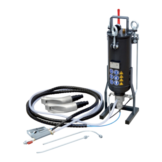
- Page 1 Granule jet blasting device PG 5–8 Owner‘s Manual 81 29 2 208 034 Translation of the original instructions...
- Page 2 This instruction manual is protected by copyright. No use outwith the strict limitations of copy- right legislation without the consent of the manufacturer is permitted, this rendering the offen- der liable to criminal prosecution. This applies likewise for the extraction of individual illustrations and the use of texts in extract form.
-
Page 3: Table Of Contents
1. Information regarding this manual 2. Permitted operators 3. Pictograph key 1. Use for intended purpose 2. Danger sources 3. Safety devices on the equipment 4. Safety measures at the installation site 1. Unpacking the device 2. Identification and description of the device components 3. -
Page 4: Information Regarding This Manual
1.1 Information regarding this manual Note Legislation stipulates that users must be trained in the use of manually operated blasting equipment. State-of-the-art The granule jet blasting device corresponds with the state of technology. To ensure that the equipment operates safely, it must be operated in a proper and safe manner. -
Page 5: Pictograph Key
1.3 Pictograph key Several sections of these operating instructions are marked Follow all in- with internationally recognised warning signs, danger notes and structions and general prohibition signs. Please comply with all notes and safety safety rules rules! The individual pictographs are explained in the following. Instruction manual Please note the following. -
Page 6: Use For Intended Purpose
2.1 Use for intended purpose The granule jet blasting device complies with the machi- nery directive 98/37 EC and is used for processing the surface of metal using a grainy blasting material, that is blasted onto the surface that is being processed. The blasting material is transported using compressed air. - Page 7 The device must only be operated using hoses that are appro- ved for the purpose of use and the operating pressure of the device. The device may only be used by trained personnel. Never throw or drop the granule jet blasting device. The granule jet blasting device may only be used at ambient temperatures of between 5 °C and 50 °C.
-
Page 8: Safety Devices On The Equipment
2.3 Safety devices on the equipment 2.3.1 2.3.2 Item B: Item A: work item relieve Fig. 2.3.1 There is a 3-way ball valve on the granule container that ap- plies compressed air to the container and the control system in the operating position. - Page 9 2.3.3 There is a 2-way ball valve on the handle of the blasting lance. Fig. 2.3.3 This can be operated if a control function fails. If the ball valve is closed, no air or other blasting material can exit from the lance.
-
Page 10: Safety Measures At The Installation Site
2.4 Safety measures at the installation site 2.4.1 Fig. 2.4.1 The surface on which the device is installed must be level, load- bearing and stable in accordance with the weight of the device. The device may only be used in combination with the suction adapters that are provided for the respective motor type and an adequately dimensioned vacuum cleaner. -
Page 11: Unpacking The Device
3.1 Unpacking the device • Place box on a level surface 3.1.1 • Open box and carefully remove the device • Check the accessories - Operating instructions - Granule container with connected hose package and handle - Straight blasting lance - Angled blasting lance - Possibly other accessories, see delivery note... -
Page 12: Device Components
3.3 Device components 3.3.1... - Page 13 Title Title Eye bolt Elbow fitting connection Annular nut Disc Hose, black Ø 6 mm O-ring Hose, blue Ø 6 mm Split pin Hose, transparent Ø 6 mm Handle Nozzle, bent Control block Granule container PVC hose Ø 14 mm Kapsto sealing screw Handle Press nipple...
-
Page 14: Technical Data
3.4 Technical Data 3.4.1 1 = Control air, transparent hose 2 = Main air, black hose 3 = Granules supply, blue hose Blasting lance, 3/3-way straight control valve Blasting lance, bent Length 290 mm Width ca. 280 mm Height 620 mm Max. -
Page 15: Operation Of The Granule Jet Blasting Device
4.1 Operation of the granule jet blasting device • Fill with blasting material. • Connect vacuum adapter to vacuum device. • Attach blasting lance to handle. • Connect granule jet blasting device to the compressed air supply. • Start the cleaning process. •... -
Page 16: Granule Jet Blasting Device Preparation And Connection
4.2 Granule jet blasting device preparation and connection 4.2.1 4.2.2 4.2.3 4.2.4 G1/4“ R1/4“ G1/4“ Ø 6 mm Fig. 4.2.1 The device is supplied from the factory without a compressed air coupling. The ball valve has a connecting thread with a female thread of G ¼“. - Page 17 4.2.5 4.2.6 ≥ Ø 6 mm 4.2.7 4.2.8 max. 8 bar 6–8 bar The device may only be operated using dry, oil-free compressed air! The granule jet blasting device may only be operated Fig. 4.2.6 with an external supply unit with variable operating pressure! The operating pressure of the device should be bet- Fig.
-
Page 18: Filling With Blasting Material
4.3 Filling with blasting material 4.3.1 4.3.2 Fig. 4.3.1 4.3.3 3-way ball valve in „Relieve“ position Fig. 4.3.2 Pressure gauge must not be indicating any pressure Fig. 4.3.3 Undo eye bolts and swivel out swivel- ling screw fitting Attention! Device may only be filled if container is de- pressurised and the air supply line has been discon- nected. - Page 19 4.3.4 4.3.5 Fig. 4.3.4 4.3.6 Remove lid of container Fig. 4.3.5 Filling with granules Fig. 4.3.6 20–30 mm Max. filling level 20–30 mm below air inlet connection Only blasting material that has been approved by the manufacturer may be used: Cleaning granulate. The blasting material must be free of impurities.
- Page 20 4.3 Filling with blasting material 4.3.7 4.3.8 Fig. 4.3.7 Check lid seal. Seal must be clean and must not be damaged. Fig. 4.3.8 Place lid on container. Fig. 4.3.9 Fit swivelling screw fitting. Fig. 4.3.10 Tighten eye bolts by hand. Fig.
- Page 21 4.3.9 4.3.10 4.3.1 1...
-
Page 22: Connect Vacuum Adapter To Vacuum Cleaner
4.4 Connect vacuum adapter to vacuum cleaner 4.4.1 4.4.2 Fig. 4.4.1 4.4.3 Attach stepped grommet of vacuum adap ter to suction hose of vacuum cleaner. Fig. 4.4.2 Remove adapter segments that are too small from stepped grommet. Fig. 4.4.3 Secure suction hose with a hose clamp Fig. -
Page 23: Attach Blasting Lance To Handle
4.5 Attach blasting lance to handle 4.5.1 4.5.2 Fig. 4.5.1 4.5.3 Screw suitable blasting lance to 2-way ball valve. Fig. 4.5.2 Move 2-way ball valve to the open position. Fig. 4.5.3 Slowly turn 3-way ball valve to the wor- king position. Fig. -
Page 24: Starting The Cleaning Process
4.6 Starting the cleaning process 4.6.1 4.6.2 Before the cleaning process is started, the operator must put on the prescri- bed protective clothing! Only trained and instructed experts may operate the device! -
Page 25: Blasting
4.7 Blasting Fig. 4.7.1 4.7.1 Blasting with air / blowing out When the pull-off lever is moved to posi- tion 1 (half-way position) only air comes out of the blasting lance. This working position is used to blow out the cleaning area. Fig. -
Page 26: Cleaning The Inlet Valves And The Inlet Channel
4.8 Cleaning the inlet valves and the inlet channel 4.8.1 4.8.2 4.8.3 4.8.4 Fig. 4.8.1 – The blasting lance must be positioned close to the surfaces that 4.8.4 are being cleaned. The cleaning phases should last no more than 2-3 seconds. Then the cleaning area should be blown out again with air. - Page 27 4.8.5 4.8.6 After all cleaning positions have been blasted once, the clea- Fig. 4.8.5 ning result must be visually inspected. If the result is unsatisfac- tory, the process must be repeated and /or the working pressu- re of the device increased. Max. 8 bar! The inlet valves and the inlet channel area should be bare Fig.
-
Page 28: Taking The Device Out Of Service
4.9 Taking the device out of service 4.9.1 4.9.2 Fig. 4.9.1 4.9.3 After each working procedure the 3-way ball valve must be moved to the „Relieve“ position. Fig. 4.9.2 The compressed air supply line can be disconnected if no pressure is being indi- cated on the pressure gauge. -
Page 29: Maintenance / Cleaning
5.1 Maintenance / cleaning 5.1.1 5.1.2 Attention! The blasting material 5.1.3 hose is also subject to wear during operation, and must be checked for damage at least every two months. The blasting material hose should be replaced once per annum if the device is used regularly! Fig. - Page 30 5.1 Maintenance / cleaning 5.1.4 5.1.5 Fig. 5.1.4, 5.1.5 5.1.6 Remove hose and replace with new hose. Fig. 5.1.6 This opportunity must be taken to check 6–7 mm all hose grommets and connecting nipp- les on the control valve and the handle. If the size of the hole has been incre- ased significantly by the flow of bla- sting material, it must be replaced!
- Page 31 5.1.7 5.1.8 Fig. 5.1.7 – 5.1.9 5.1.9 At regular intervals, but after no more than 10–15 container fillings, the filter in- serts in the blasting material container and the lid of the device must be clea- ned! Fig. 5.1.10 Unscrew all filter inserts and blow them out with a compressed air blow-out gun from threaded side until all granule or dust residue has been removed.
-
Page 32: Spare Parts And Accessories For The
5.2 Spare parts and accessories for the PG 5–8 granule jet blasting device... - Page 33 Pos.No. Item number Title SER-GPG-00000128 Annular nut SER-GPG-00000129 Exhaust valve SER-GPG-00000130 GE 1/8“ thread to Ø6 SER-GPG-00000131 GE 1/4“ thread to Ø6 SER-GPG-00000132 Double nipple 1/4“ SER-GPG-00000133 Pressure gauge SER-GPG-00000134 Angle connector 1/8“ SER-GPG-00000135 Relief valve SER-GPG-00000136 T-piece SER-GPG-00000137 3-way ball valve SER-GPG-00000138 2-way ball valve SER-GPG-00000139...
-
Page 34: Warranty Conditions
5.2 Warranty conditions This device complies with the current safety regulations and was tested before leaving the factory. We provide a 24 month warranty and are obliged to carry out all repairs caused by material and/or manufacturing faults that become necessary during this time. -
Page 35: Eu Declaration Of Conformity
Thorsten Weyland Equipment type: Pneumatically operated granule jet blasting device Type designation: PG 5-8 Has been developed and designed in accordance with the standards and guidelines of TKR Spezialwerkzeuge GmbH Am Waldesrand 9–11 58285 Gevelsberg (Germany) Serial number range: 00001–10000... - Page 36 Am Waldesrand 9–11 D-58285 Gevelsberg (Germany) Phone +49 2332 66607-0 +49 2332 66607-941 E-mail info@tkrgroup.com Internet www.tkrgroup.com...
Need help?
Do you have a question about the PG 5-8 and is the answer not in the manual?
Questions and answers