Table of Contents
Advertisement
Quick Links
INSTRUCTION MANUAL
INSTALLATION | WIRING | COMMISSIONING | MAINTENANCE |
I S O 9 0 0 1
ISO 14001
Q u a l i t é
Environnement
AFNOR CERTIFICATION
AFNOR CERTIFICATION
JBRB ECOWATT
®
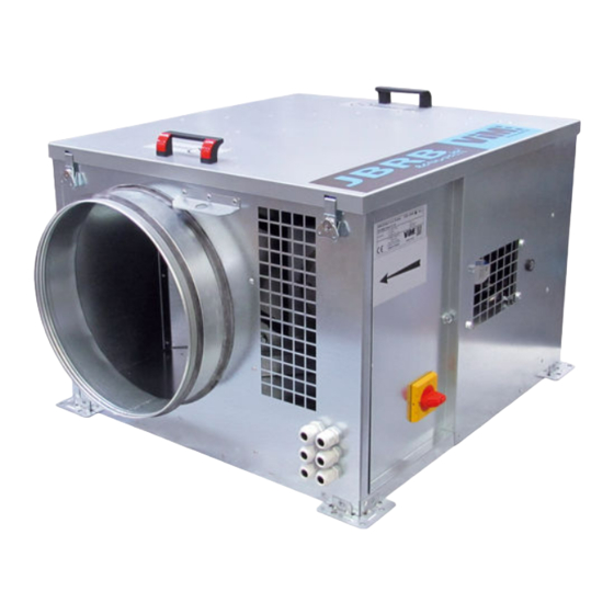
Tertiary buildings ventilation ECM motor extractor unit
400°C 1/2hr C4 approved
Efectis certificate : EFR-16-002341
VENTIDRIVE Controller
NT00000704-JBRB-ECOWATT-AN-210301
Advertisement
Table of Contents

Related Manuals for ViM JBRB ECOWATT


Summary of Contents for ViM JBRB ECOWATT
- Page 1 I S O 9 0 0 1 ISO 14001 Q u a l i t é Environnement AFNOR CERTIFICATION AFNOR CERTIFICATION JBRB ECOWATT ® Tertiary buildings ventilation ECM motor extractor unit 400°C 1/2hr C4 approved Efectis certificate : EFR-16-002341 VENTIDRIVE Controller...
-
Page 2: Table Of Contents
CONTENTS GENERAL INFORMATION ........................ 3 Warnings ..........................3 Safety instructions ........................3 Reception - Storage........................3 Warranty ..........................4 PRODUCT PRESENTATION ......................4 Description..........................4 Aeraulic curves ........................5 INSTALLATION ..........................7 Dimensions and weight ......................7 Handling ..........................11 Choice of location ........................11 Ceiling-mounted installation .................... -
Page 3: General Information
® JBRB ECOWATT units are intended for controlled mechanical ventilation or air recycling applications on tertiary premises: •... -
Page 4: Product Presentation
In any case, maker is not responsible for transformed material, even partially repaired. PRODUCT PRESENTATION 2.1 Description The certificate number certifies that the JBRB ECOWATT ® range complies with the order of 22 March 2004 of the French Interior Ministry. -
Page 5: Aeraulic Curves
2.2 Aeraulic curves JBRB ECOWATT JBRB ECOWATT ® ® P (Pa) P (Pa) stat Pabs (W) stat Pabs (W) 100% 100% Qv (m Qv (m JBRB ECOWATT JBRB ECOWATT ® ® P (Pa) P (Pa) stat Pabs (W) stat Pabs (W) - Page 6 JBRB ECOWATT JBRB ECOWATT ® ® ∆P (Pa) ∆P (Pa) Pabs (W) Pabs (W) stat stat 1400 1000 100% 1200 100% 1000 Qv (m Qv (m 1000 2000 3000 4000 5000 6000 1000 2000 3000 4000 5000 6000 7000 8000...
-
Page 7: Installation
INSTALLATION 3.1 Dimensions and weight JBRB ECOWATT 04 / 06 / 10 / 22 / 30 / 38 - horizontal discharge - L / M configuration ® Sense of the air Sense of the air Sense of the air ----- Only available on modular version (M configuration). - Page 8 JBRB ECOWATT 10 / 22 / 38 - horizontal discharge - D configuration ® Sense of the air Sense of the air Sense of the air Model Weight (kg) JBRB ECOWATT 10 815 ® JBRB ECOWATT 22 1,048 ® JBRB ECOWATT...
- Page 9 JBRB ECOWATT 04 / 06 / 10 / 22 / 30 / 38 - vertical discharge - L / M configuration ® Sense of the air Sense of the air Sense of the air ----- Only available on modular version (M configuration).
- Page 10 JBRB ECOWATT 10 / 22 / 38 - vertical discharge - D configuration ® Sense of the air Sense of the air Sense of the air Model Weight (kg) JBRB ECOWATT 10 804 ® JBRB ECOWATT 22 1,037 ® JBRB ECOWATT...
-
Page 11: Handling
3.2 Handling N.B.: Do not use the plastic handles to move the unit. These handles are only to open the unit cover. JBRB ECOWATT 04 to 38 JBRB ECOWATT 48 to 92 ® ® 3.3 Choice of location JBRB ECOWATT... -
Page 12: Ceiling-Mounted Installation
3.4 Ceiling-mounted installation JBRB ECOWATT 04 to 38 Ceiling-mounted installation ® ® JBRB ECOWATT 04 to 38 can be installed with the cover facing downwards. • Air space of at least 100mm must be main- tained between the unit and the horizontal sur- face on which it is set up. -
Page 13: Aeraulic Connection
Do not turn off the device by directly shutting off the controller’s power supply via the INTZ or shutting off the mains power supply. Short circuit protection ® The JBRB ECOWATT power supply must have a short circuit protection. The short circuit protection equipment must at least have a "C" curve trigger according to IEC 60898-1. 13/28... -
Page 14: Electrical Features
5.2 Electrical features Single-phase 230V Three-phase 400V Size Input power I. Max Input power I. Max Turbine Turbine (kW) (kW) JBRB ECOWATT ® 0.07 JBRB ECOWATT ® 0.13 JBRB ECOWATT ® 0.15 JBRB ECOWATT ® 0.35 JBRB ECOWATT 0.60 0.60 ®... -
Page 15: Description Of The Drive For Model 30 To 92
5.4 Description of the drive for model 30 to 92 Factory- tted motor terminal block Running status LED It is imperative that the U-V-W Factory- tted terminal block cable sequence is observed. One-phase Three-phase N PE L1 L2 U V W PE BR- BR+ R2 No Terminal block accessible... -
Page 16: Pressure Switch Connection
5.5 Pressure switch connection • Open the unit panel by unscrewing both screws with a 13mm spanner. • Add the 2nd cable gland to the cable. • Open the pressure switch cowl and connect the wires. • Access to terminals and settings •... - Page 17 Alarms table Alarms view Trigger Motor function / action Power supply too low The power supply is too low Reduced performance Stop of the motor after 5 restarts caused Power supply too high The power supply is too high by the same default during 60 minutes Electronic internal temperature too high The ambient temperature is too high Reduced performance...
-
Page 18: Relay Functioning
5.7 Relay functioning Relays characteristics Max 1A under 30VDC and 24 VAC The Output 1 relay is a running relay. The relay switches when the run signal is given. The Output 2 relay is a fault relay. The relay switches when the motor stops after 5 attempts of restart. CONTROLLER TERMINALS Fault or power o indicator R2 No... -
Page 19: Reb Ecowatt
• Speed set by remote potentiometer, select the desired curve by referring to § "2.2 Aeraulic curves", page 5. • Disconnect the potentiometer built into the unit to connect the “CVF or REB ECOWATT ® ” remote potentiometer instead. JBRB ECOWATT 04 to 22 single-phase wiring ® Lockable safety switch REB ECOWATT®... -
Page 20: Bcca 1V External Start/Stop Control Electrical Connection In Parallel Of The Internal Potentiometer
• Speed set by remote potentiometer, select the desired curve by referring to §"2.2 Aeraulic curves", page 5 ® • The BCCA 1V external Start/Stop control enables to stop the JBRB ECOWATT cabinet fan without modifying the initial airflow/pressure step point. -
Page 21: Electrical Wiring Of The Etdz (Tactile Command)
5.10 Electrical wiring of the ETDZ (tactile command) ETDZ wires on the RJ12 “A” Modbus connector of the terminal block. ETDZ (optional tactile command) allows to set the fan start or stop and to adjust the setpoint. ETDZ CONTROLLER TERMINALS Setpoint 0% Current speed _ _ _ RPM Drive type PM... - Page 22 CVF remote control. By default, the unit is set to its maximum speed, in bold in the table below. The po- tentiometer built into the unit is used to modify the turbine’s speed to set the airflow. Potentiometer graduation and speed correlation chart JBRB ECOWATT speed (in rpm) Setpoint ®...
-
Page 23: Maintenance
Check aeraulic connections Check operation Auxiliary fan Check operation using test button Check operation using test button 7.3 Access to electric fan JBRB ECOWATT 04 to 38 ® JBRB ECOWATT 48 to 92 ® To access all the unit compartments, unfasten the 4 latches, then remove the unit cover using the handles. -
Page 24: Electric Fan Replacement
7.4 Electric fan replacement 7.4.1 JBRB ECOWATT 04 to 22 ® • Switch off the power supply. • Unfasten the 2 door bolts, then remove the door. • Disconnect the power cable from the on-off switch. • Unfasten the 4 latches, then remove the unit cover using the handles. - Page 25 7.4.2 JBRB ECOWATT 30 to 92 ® A ( 1 : 1 ) • Switch off the power supply. • Unscrew the 2 door screws, then remove the door. • Disconnect the on-off switch power cable. • Unfasten the 4 latches, then remove the unit cover using the handles.
-
Page 26: Spare Parts
Motor turbine Spare motor turbine for JBRB ECOWATT 263209 ® Motor turbine Spare motor turbine for JBRB ECOWATT ® VENTIDRIVE 0,5kW - Drive for JBRB ECOWATT 30 single- 1571200001 Drive phase VENTIDRIVE 1,5kW -Drive for JBRB ECOWATT ® 30 Three-... - Page 27 27/28 NT00000704-JBRB-ECOWATT-AN-210301...
- Page 28 Les prés de Mégy Sud – SOUDAN CS 60120 - 79401 ST MAIXENT L’ECOLE CEDEX Tel.: 05 49 06 60 38 or 05 49 06 60 25 – Fax: 05 49 06 60 36 sav@vim.fr - www.vim.fr 28/28 NT00000704-JBRB-ECOWATT-AN-210301...
Need help?
Do you have a question about the JBRB ECOWATT and is the answer not in the manual?
Questions and answers