Table of Contents
Advertisement
Quick Links
Big Bale Transtacker Operators Manual (DWA-FWA Included)
Operation and Maintenance Manual
Please read and follow all instructions before operating the machine
It is the responsibility of the operator to read and understand the contents of
this manual in full before operating the machine for the first time.
The Operators Manual must accompany the machine at all times. If the
machine is resold, the Operators Manual must be given to the new owners
with the machine.
1
Advertisement
Table of Contents

Subscribe to Our Youtube Channel
Summary of Contents for BIG BALE Transtacker
- Page 1 Big Bale Transtacker Operators Manual (DWA-FWA Included) Operation and Maintenance Manual Please read and follow all instructions before operating the machine It is the responsibility of the operator to read and understand the contents of this manual in full before operating the machine for the first time.
-
Page 2: Table Of Contents
To return to work screen from this screen, press the ‘Enter’ button located on the bottom right of the screen..................16 5.3 Loading bales onto your Transtacker ..................16 5.3.1 Opening the Transtacker for Loading .................. 16 5.3.2 Use of Forks .......................... - Page 3 5.3.9 Auto Lower Turntable ......................27 5.3.10 Completing a Load ......................27 5.4 Tipping a Full Load ........................28 5.4.1 Tipping up the trailer and manually releasing stack ............28 5.4.2 Stacking against previous stacks ..................30 5.4.3 Auto Open ..........................31 It’s advised that if you use this function, you need to be confident the stack is vertical and secure before releasing it.
- Page 4 7.2.2 System Pressure ........................55 Software Diagrams........................56 8.1 Auto Pickup Sequence ........................ 57 8.2 Auto Stack Sequence (Both with and without tie) ..............58 8.3 Auto Lower Turntable ......................... 59 8.4 Auto Open Sequence ........................60 8.5 Auto Tip Bed Down Sequence ..................... 61 8.6 Road Mode Sequence .........................
-
Page 5: Introduction
1.3 Intended Use of the Machine The Big Bale Transtacker is designed to collect bales of various widths and depths (approx. 2.4m ± 0.1m in length. ) into completed stacks, and erect them into a tower. -
Page 6: Specification
**In order to fit 12 of 1.2 x 1.3m bales, the bales must be rotated so strings are on the side of the bale. To achieve this, there must be either a quarter turn chute for the bales or a wheel baler turner which is fitted on the tractor’s front linkage. Both are available from Big Bale Co. South Ltd. -
Page 7: Machine Overview
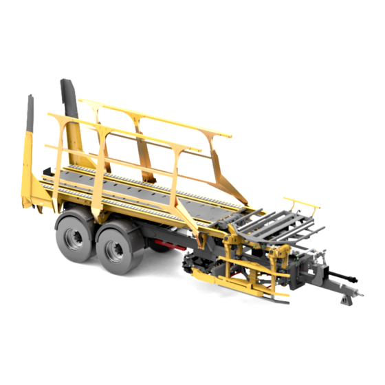
3.0 Machine Overview Figure 1: Transtacker Overview... -
Page 8: Safety Of Transtacker
WARNING: Read Owner’s Manual This manual contains safety information, operation instructions and maintenance instructions for the Big Bale Transtacker. The operator must ensure they have read the manual in full and have a full understanding of this manual before operating the machine. -
Page 9: Operation Of Transtacker
Once installed, turn the tractor cautiously initially and ensure the tractor links, etc. do not make contract with any part of the Transtacker and that there is sufficient clearance for the hoses and PTO. It is advised to remove link arms where practical. -
Page 10: Joystick Functionality
• The female circular aluminium connector plugs into the male circular aluminium connector, located on the tool post of the Transtacker. 5.2.3 Joystick Functionality To operate functions, refer to Table 4 to choose the function you wish to select. Where a button is specified you must push and hold the button and push the joystick in the direction instructed. -
Page 11: Transtacker Control Modes
Insert Hooks 5.2.4 Transtacker Control Modes There are three modes for the Transtacker: Field Mode, Stack Mode and Road Mode. ‘Field Mode’ is for loading of the Transtacker in the field. ‘Stack Mode’ is for unloading and recollecting of stacks. - Page 12 The mode is specified in the top left-hand corner of the screen (see blue arrow in Figure 4). To interchange between ‘Field Mode’ and ‘Stack Mode’, you can either press the top right-hand button on the joystick (see Figure 3) or press the bottom right button on the screen (see green arrow in Figure 4).
-
Page 13: Screen Functionality
Figure 6: Leaving Road Mode 5.2.5 Screen functionality This section explains the use of the screen and the purpose of each button. When you first turn on your screen, you will be met with the screensaver screen shown in Figure 7. To get to the work screen, press any button on the joystick. - Page 14 Table 5: Screen Symbols Explained Symbol Function ‘Road Mode’ selection. Bale count page. This symbol turns the text on the ‘Field Mode’ and ‘Stack Mode’ screens. This symbol shows the mode it would change to if the corresponding joystick or screen button is pressed.
-
Page 15: Bale Layout Symbols And Deletion
Figure 9. Once familiar with the Transtacker, the bale display is very useful to aid with planning a route around the field. You will know the total number of layers on the machine and therefore how many more layers and/or bales are required meaning you can plan the most efficient route to collect the remaining number of bales to fill the trailer. -
Page 16: Bale Count Screen
5.3 Loading bales onto your Transtacker 5.3.1 Opening the Transtacker for Loading Having entered the field and you now need to open up the Transtacker ready to collect bales as follows: 1. Exit ‘Road Mode’ and enter ‘Field Mode’ (see section 5.2.4). Now you will need to engage the PTO and do the following steps to open the Transtacker. -
Page 17: Use Of Forks
5.3.2 Use of Forks The forks are only required for bales less than 0.8m high or when working on particularly steep ground. The forks on the Transtacker arrive bolted down, see section 6.1.3 to unbolt the forks/bolt back down the forks. -
Page 18: Auto Pickup Operation
Figure 14: Forks Forward 2. Press the bottom right button and push joystick forward to pull the forks to the front of the platform (Figure 14). Figure 15: Forks Raise 3. Holding the bottom right button and pull the joystick backwards to raise the forks. Once the forks are fully raised, they are ready for use (Figure 15). -
Page 19: Picking Up A Bale Manually
2. Once the bale is in the correct position, tight to the pickup and against the Guidebar. Push the joystick forward and then release (assumed you’re already in field mode). This will pick the bale up and place on the Turntable for you (Figure 16). o Should you wish to stop the automated sequence at any point, just push the joystick left or right and this will cancel the function and the machine will await operator input. - Page 20 Figure 17: Insert Tines 2. When the bale is in the correct position, press the top left button and push to the right to ‘Insert Tines’ until the tines penetrate the bale sufficiently (Figure 17). Figure 18: Pickup Raise 4. Press and hold the top left button and move joystick forward and the pickup will lift the bale (Figure 18).
-
Page 21: Auto Stack With Tie Operation
Figure 20: Insert Hooks 6. Press and hold the bottom right button and move joystick right to insert hooks into the bale (Figure 20). Figure 21: Lower Pickup 7. Press and hold the top left button and move the joystick backwards to lower the pickup to its home position (Figure 21). -
Page 22: Auto Stack With No Tie Operation
Figure 22: Auto Stack with Tie 1. Move the joystick backwards and release it (Figure 22). The machine will place the first line of bales on the platform against the forks and return to its home position in this sequence. a. -
Page 23: Combined Auto Pickup And Auto Stack
5.3.7 Combined Auto Pickup and Auto Stack The Transtacker has a feature where you can pickup another bale and the pickup will hold and carry that bale at the ‘Pickup Hold Angle’ while the ‘Auto Stack’ is already operating. Once the ‘Auto Stack’... - Page 24 Figure 26: Insert Hooks 1. Check if the hooks are inserted into the bales. If hooks need inserting, press the bottom right button and push the joystick to the right to hook the bales (Figure 26). Figure 27: Raise Stack Table 2.
- Page 25 6. Hold down the middle button and move the joystick right to extend the turntable further forward (Figure 28). a. NOTE: IT IS THE OPERATOR’S RESPONSIBILTY TO ENSURE TRANSTACKER MAINTAINS SAFE DISTANCE FROM TRACTOR CAB. 7. Hold down the bottom right button and move joystick forward to raise the Turntable to 90 (Figure 27).
- Page 26 Figure 31: Retract Hooks 9. Hold down the middle button and push the joystick forward to retract the hooks from the bales (Figure 31). a. NOTE: If working on sloping ground, it is advised to close the side gates before going any further in this sequence.
-
Page 27: Auto Lower Turntable
Figure 35: Bale Layout Background showing blue as trailer is 'Full'. For rolled bale sizes 0.8x0.9m, 1.2x0.9m and 1.3x1.2m, the Transtacker can carry an additional layer by changing the ‘Extra Layer’ setting to ‘Active’. Table 3 shows you the different number of bales you... -
Page 28: Tipping A Full Load
This section explains the process of tipping a trailer. 5.4.1 Tipping up the trailer and manually releasing stack Manoeuvre the Transtacker to the stack site and ensure the following: • The ground is firm and flat with slopes of no more than 5 degrees. - Page 29 Figure 38: Retract Hooks 7. Hold the middle button and push forward to release the hooks (Figure 38). Figure 39: Lower Stack Table 8. Keep the middle button held down and move the joystick left to lift the Turntable off the stack and to lower the Turntable to approximately 45 degrees (Figure 39).
-
Page 30: Stacking Against Previous Stacks
3. Reverse slowly until the you feel the trailer make contact with the existing stack. Using the Transtacker mudguard as a reference, pull forward approximately 8-9 tyre cleats and then proceed to tip the trailer up. This should give you a relatively tight stack. Depending on ground, adjust number of cleats in order to get stack to satisfactory tightness between stacks. -
Page 31: Auto Open
time, and depending on the gradient of the ground, you may need a gap up to 0.3m at the bottom of the stack in order for the stack to be vertical and tight at the top. 5.4.3 Auto Open ‘Auto-Open’ has two purposes. Firstly, the auto function can be used to release the stack rather than doing it manually, as instructed in section 5.4.1. -
Page 32: Auto Tip Bed Down
5.4.5 Auto Tip Bed Down Once the Transtacker is clear of the stack, the ‘Auto Tip Bed Down’ function can be used to bring the Transtacker platform back down automatically. This function is in ‘Stack Mode’. To access it, hold the bottom left button and push joysticks forwards and release. -
Page 33: Retrieving An Erected Stack
To make it easier to retrieve a stack it is advised that stacks are tied together. 1. If necessary, exit ‘Road Mode’ and put Transtacker into ‘Stack Mode’. 2. Hold down either the top left button and push the joystick forward or press the bottom left button and pull back the joystick to start the ‘Auto Open’... - Page 34 Figure 48: Raise Stack Table 5. Hold down the bottom right button and move the joystick forward to raise the Turntable to be perpendicular to the Platform (Figure 48). a. NOTE: The Turntable must be parallel to the bales (fully raised) before retracting the Turntable onto the top of the stack, as this could cause damage to the Turntable.
- Page 35 8. Hold down the bottom right button and move joystick back to close the rear clamps (Figure 51). a. Be aware that if the trailer is over vertical, the rear clamps will get full of soil and will not be able to clamp the bales as intended. Figure 52: Tip Bed Down 9.
-
Page 36: Adjustments
6.0 Adjustments This section covers all forms of adjustments to the Transtacker in order for the machine to perform efficiently and as intended. 6.1 Mechanical Adjustments This section covers all the necessary mechanical adjustments between bale sizes and a step by step guide on how to carry out the adjustments. -
Page 37: Pickup Height Plates For Corresponding Bale Size
6.1.2 Pickup Height Plates for corresponding bale size The pickup is mounted on to the chassis by 2 vertical square posts that slide vertically in brackets on the chassis. The height of the pickup is dictated by pins and plates inserted through holes in the 2 vertical square posts. -
Page 38: Forks - Bolting Down/Releasing
NOTE: Should you choose to operate with the forks bolted down, there is a setting in ‘Extra Settings’ called ‘Forks Forward Timer’ which can be reduced to speed up the ‘Auto-Closing’ function of the Transtacker (see section 6.3.3). 6.1.4 Number of tines and their positioning This section gives you some basic idea of tine positions and the weight each tine can withstand. -
Page 39: Pickup Shoe Adjustment
6.1.5 Pickup Shoe adjustment The Pickup Shoe is the black bar on the bottom of the pickup. It is generally only needed when picking up 1.2x1.3m bales as the tines will be higher in the bale in order for the pickup height to be correct for the Turntable. -
Page 40: Settings Explained
This section explains the functions of all the settings. Should you wish to adjust any setting, this section explains the effects and the possible unexpected side effect that could disrupt the behaviour of the Transtacker. To find the settings, press the bottom left button with the three white lines to take you to the first settings page (see Figure 56). - Page 41 NOTE: The top left symbol is for day/night mode. This will reduce the screen brightness for working in the dark. Figure 57: Manual Setting Screen Layout Table 6: List of all Manual Settings, there function and default value Default Button Name Setting Name Function Value (%)
-
Page 42: Auto Settings
Manual Stack Table Lower The speed the Stack Table Speed Lowers. Manual Stack Table Rotate The Speed the Stack Table Speed Rotates both CW and ACW. Trailer Settings Manual Raise Trailer Speed Speed the Trailer Raises. Manual Lower Trailer Speed Speed the Trailer Lowers. - Page 43 Figure 59: Auto Settings Screen...
- Page 44 Table 7: List of Auto Functions, their functions and default values Default Value Button Name Setting Name Function (% or s) Tine Settings Auto Insert Tines Timer How long the pickup tines ‘Insert’ for during the auto pickup cycle • How long the pickup tines ‘Retract’...
- Page 45 • Time taken for hooks to ‘Retract’ during ‘Auto-Stack’ sequence • Time taken for hooks to ‘Retract’ during ‘Auto-Tip Bed Down’ sequence Auto Extend Hooks Timer • Time taken for hooks to ‘Insert’ during ‘Auto-Pickup’ sequence Pickup Auto Lower Pickup Speed Maximum speed the pickup will travel during ‘Auto-Pickup’...
-
Page 46: Speed/Angle Settings
6.3.3 Speed/Angle Settings This page gives you adjustments to the ‘speed reductions’ or proportional speed control of pickup lift/lower, turntable lift/lower and turntable rotate clockwise/anticlockwise. It is advised that without a competent operator, none of these settings should be changed. These proportional speed reduction settings slow down the beginning and end of the cylinder strokes to make the machine smoother in operation and exerts less stress on the machine. - Page 47 • The angle from 90 degrees which the Turntable rotation will decelerate • The speed the Turntable Rotate CW rotation will initially start at • Minimum Speed The speed the Turntable rotation will finish at • The speed the Turntable Rotate ACW rotation will initially start at •...
-
Page 48: Additional Settings
When you push the joystick forward in Extend Tines in the in the lower pickup stage of the ACTIVE Bump ‘Auto-Pickup’ sequence, the tines will come in when this setting is ‘ACTIVE’ • The minimum angle the Turntable rotate can happen at during auto functions Minimum Table Lift •... -
Page 49: Sensor Adjustment And Calibration
6.4 Sensor Adjustment and Calibration On the Transtacker there are a total of 7 sensors, 3 potentiometers and 4 inductive switches used in the automated sequences. 6.4.1 Potentiometer Sensors There are 3 potentiometer sensors and their locations are shown in Figure 62. They perform the following functions: •... - Page 50 Transtacker. Ensure the Guidebar is extended in order to use the ‘Pickup Angle’. NOTE: The Transtacker will move and therefore you need to ensure the area is safe and clear of bystanders. NOTE: Before you rotate the turntable, ensure the turntable is raised to at least 15 degrees.
-
Page 51: Calibration Of Potentiometers
‘Stack Mode’, press the bottom right button and push the joystick forward. 6.4.3 Inductive Switches and adjustment There are four inductive sensors located around the Transtacker that are used in auto functions. The locations around the Transtacker are shown in Figure 66 and their names and functions are explained... - Page 52 ‘Auto Lower Turntable’ functions. In the ‘Auto Tip Bed Down Function’, it senses when the platform is lowered on the Stops. Figure 66: Location of Inductive Switches on Transtacker The status of the sensors is shown on the ‘Sensor Status’ page in Figure 63. The 4 sensors all have coloured dots next to them denoting their status.
- Page 53 To adjust the sensors, simply loosen the two nuts on the sensor and move the sensor closer or further away from the ‘target’. It is advised that target is a minimum of 2mm away from the sensor but no more than 6mm away. To know the sensor is close enough to the LED, the LED will be lit orange. if the LED is flashing orange, the sensor is at its limit of 8mm and needs to be adjusted closer.
-
Page 54: Electrical And Hydraulic System
F7 – 5A Supply of power to E-stop 7.2 Hydraulic System This section outlines the hydraulic system of a Transtacker, highlighting maintenance points and check points around the machine. The Transtacker contains its own hydraulic system, including pump and tank. -
Page 55: Hydraulic Filters
Pressure Filter every other year. 7.2.2 System Pressure The maximum hydraulic pressure of a Transtacker is 210bar. This information is relevant should you need to replace any hydraulic hoses. The grade of oil required is Hydraulic 46. -
Page 56: Software Diagrams
8.0 Software Diagrams. To aid with diagnostics, the software diagrams should help the operator locate where the issue within the auto sequence and combined with section 9.0 Troubleshooting may help resolve the issue. The software diagrams in this section only apply to the auto functions. By using diagrams and the top right corner of the screen (Figure 8), along with the key below (Table 10), you should be able to fault find or fine tune the machine. -
Page 57: Auto Pickup Sequence
8.1 Auto Pickup Sequence Figure 69: Auto Pickup Diagram... -
Page 58: Auto Stack Sequence (Both With And Without Tie)
8.2 Auto Stack Sequence (both with and without tie) Figure 70: Auto Stack Diagram... -
Page 59: Auto Lower Turntable
8.3 Auto Lower Turntable Figure 71: Auto Lower Turntable Diagram... -
Page 60: Auto Open Sequence
8.4 Auto Open Sequence Figure 72: Auto Open Diagram... -
Page 61: Auto Tip Bed Down Sequence
8.5 Auto Tip Bed Down Sequence Figure 73: Auto Tip Bed Down Diagram... -
Page 62: Road Mode Sequence
8.6 Road Mode Sequence Figure 74: Road Mode Diagram... -
Page 63: Troubleshooting
9.1 Sensor Banner The Transtacker has an inbuilt function to detect its own sensor issues. When it detects an error and you try to use an auto function, a banner will be displayed across the top of the screen(as shown in Figure 75). -
Page 64: Inductive Switch Error
These table lists possible faults/adjustments that could happen to the Transtacker. Should you have an auto function fault that isn’t listed, you can follow the relevant auto function sequence using the software diagram in section 8 or alternatively contact the Service Department at Big Bale Co. South Ltd. - Page 65 • Check the ‘Overall Angle Tolerance’. Increase the tolerance to 2 degrees • Check the value of Pickup POT in ‘Sensor Status’ and compare to ‘Pickup Release Angle’ Pickup raises the bale up but doesn’t retract • Turntable Bale Stop may need sliding the tines out to allow bales to be pushed on further...
-
Page 66: Auto Stack Issues
Check ‘Overall Angle Tolerance’. Increase tolerance to 2 degrees • Bed Full switch is on (shows green on The Transtacker closes up when trailer isn’t full ‘Sensor Status’ page) • Check the ‘Bed Down, Table Retracted Prox’, is ‘made’ at this point which... -
Page 67: Miscellaneous Issues
9.2.3 Miscellaneous Issues Table 13: Miscellaneous troubleshooting Symptom Cause • All functions are slow in operation regardless of Standby pressure is too low, standby joystick position (LS) pressure should be 20 bar • Side gates keep stopping when opening and will Anti-Burst Valves on side gate cylinders open if you decrease manual flow rate need adjusting to allow more oil flow...
Need help?
Do you have a question about the Transtacker and is the answer not in the manual?
Questions and answers