
Summary of Contents for Preston FI + Z
- Page 1 F I + Z Lens Control Rev 1.0 Preston Cinema Systems 1659 Eleventh Street Santa Monica, CA 90404...
-
Page 2: Table Of Contents
Table Of Contents I. Introduction A. System B. Hand Unit C. MDR II. Set-Up Instructions A. Cable Operation B. Wireless Operation III. Hand Operation a. Functions b. Operations IV. MDR-2 Operation V. Digital Motors VI. Camera and Lens Installation VII. Battery Packs and Charger Unit VIII. -
Page 3: Introduction
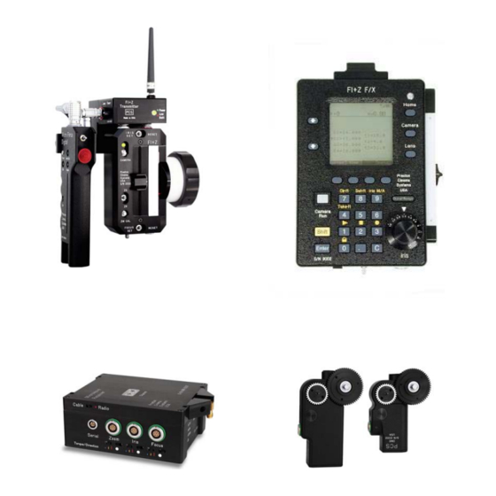
I. Introduction A. System. The F I +Z II Lens Control System provides the highest resolution position and velocity control available. The basic hard-wired system consists of the Hand Unit, Motor Driver, and Digital Motors. The addition of the Microwave Link enables complete wireless control of all functions. -
Page 4: Hand Unit
fig1. Hand Unit Zoom Mode Switch Fig.2 Hand Unit Zoom Mode Switch... - Page 5 B. Hand Unit The Hand Unit transmits Focus, Iris, and Zoom (when a Micro Force is fitted) data to the MDR2 unit. This digital data can be sent either through a cable connection using the Command cable, or in wireless mode using the ML2 Microwave link. Power for the Hand unit is provided through the Command cable when a cable link is used or from the NMH battery pack when used in the wireless mode.
- Page 6 C. MDR-2 Fig.3 MDR-2 with Microwave Transceiver The 3 Channel Motor Driver (MDR2) uses a lens calibration sequence to automatically determine the mechanical limits of the zoom, focus, and iris rings of the lens. This sequence is initiated whenever the Reset button on the MDR is pressed, or whenever a motor is connected to the Motor Driver.
-
Page 7: Cable Operation
program should now report that it has found a connection to the MDR2 and asks whether you want to proceed with the update. Choose yes. After the program has completed the update, you can remove the serial cable from the MDR2. II. -
Page 8: Hand Operation
12. Slide a charged battery into the rear of the Transmitter. The Battery Release will prevent the battery from being accidentally released. 13. Set the Channel Switches on the Transmitter and Transceiver to the same channel. There are 30 channels available (00 – 29). Channels above 30 simply repeat the same channels (i.e. - Page 9 The Zoom Cal button provides automatic adjustment for electrical offsets in the zoom control (i.e. the control is out of adjustment). If any creep of the zoom is observed, momentarily press the Zoom Cal button while holding the Micro Force in its normal operating position without any force applied to the red joystick knob The Camera Run push-button switch allows control of cameras requiring either momentary pulses (Arri 24V cameras, Sony video cameras) or those requiring a constant control voltage...
-
Page 10: Functions
A socket is provided at the bottom of the FIZ control for an external Iris control. When the external iris control is connected the slide control on the FIZ will be disabled. Fig5. Remote Iris Box p/n 4020 IV. MOTOR DRIVER FUNCTIONS The Motor Driver 2 (MDR2) is responsible for driving the motors, providing control signals to the camera, and transferring camera operating data to the wireless network through the transceiver module. -
Page 11: Digital Motors
1. Load the installation files provided on the Firmware Upgrade Installation Program CD to the PC. The update files will be installed in the folder C:\Program Files\Preston 2. Open the file containing the Firmware update. The PC screen will show the message: “Connect MDR to a serial port”... -
Page 12: Camera And Lens Installation
Step-up gears are provided to allow the DM-1, and DM-2 motors to drive Panavision Zoom and Iris gears as well as the Focus, Iris, and Zoom gears of Canon and Fujinon video lenses. Please consult our price list for a complete list of available gears. VI. -
Page 13: Battery Packs And Charger Unit
are provided for : Panavision Zoom (48 DP 20 degree PA), Panavision Iris (64 DP 20 degree PA ), Panavision Focus (32 DP, 14.5 degree PA.), .60m, .70m . A lightweight bracket for Panavision cameras is available (p/n 4341). It is secured to the post adjacent to the lens mount, and allows up to two motors to be rigidly supported with short swing arms. -
Page 14: Technical Information
The TEMP LED will glow if attempting to fast charge a battery pack outside safe temperature limits. The minimum and maximum temperatures for fast charging are 10 C (50 F) and 50 C (122 F). VIII. TECHNICAL INFORMATION Connector Pin-outs Receptacle Views –... -
Page 15: Transmitter Channels And Frequencies
iii. Motor Serial 1. Motor (+) 1. RS232 in 2. Motor(-) 2. Gnd 3. Encoder A 3. RS232 out 4. +5V 5. GND 6. Encoder 7. Motor Plugged/ ID a. Hand Unit Connectors Command i. Zoom i. Remote iris 1. Gnd +12V 1. -
Page 16: Power Requirements
3. Compliance Information This device complies with Part 15 of the FCC rules. Operation is subject to the following two conditions: This device must not cause harmful interference and This device must accept any interference received including interference that may cause undesired operation. - Page 17 The calibration and run currents for the 3 channels are: IRIS: 650mA/900 mA FOCUS: 900 mA/ 1.2 A ZOOM: 800mA/1.2A To protect the motor from overheating due to a sustained stall condition, the processor will shut down motor drive if a motor is stalled for more than approximately 5 seconds. The system can be reset by either removing power momentarily or by unplugging and re- plugging the LEMO connector going to the motor.
- Page 18 If the unit is working normally with the red LED, the microprocessor may not be making good contact with its socket. The processor contacts require cleaning with an anti-oxidant (Pro-Gold). This procedure requires careful disassembly and should be left to our Service Department. 4.
Need help?
Do you have a question about the FI + Z and is the answer not in the manual?
Questions and answers