
Related Manuals for Technische Alternative CAN-EZ3


Summary of Contents for Technische Alternative CAN-EZ3
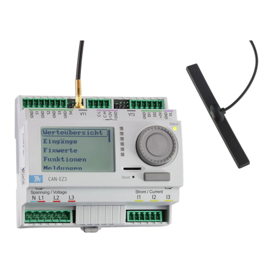
- Page 1 CAN-EZ3 CAN ENERGY METER General information Installation and connection Relevant functions Manual Version 1.07.4 English...
-
Page 2: Table Of Contents
General connection of the CAN-EZ3 ........ - Page 3 Table of contents Date / time / location ............47 Value summary .
- Page 4 Table of contents DL bus address and DL bus index ..........72 Designation .
-
Page 6: Safety Requirements
Safety requirements All installation and wiring work on the controller must only be carried out in a zero volt state. The opening, connection and commissioning of the device may only be carried out by competent personnel. While doing so, they must observe all local safety re- quirements. -
Page 7: Function Description
DHW storage, instead of exporting it to the mains, which can be less profitable. As the CAN-EZ3 has the full functionality of the x2 series and multiple sensor inputs, other tasks such as heat and energy metering are also possible. However, only specific functions are used for the ac- tual purpose of the energy meter and these are described in these instructions. -
Page 8: Installation And Connection
The CAN-EZ3 is supplied with power via the voltage measuring connection U1 (first phase). Time stamp The CAN-EZ3 has a real time clock and, as node 1 in the CAN bus network, can therefore transmit the time and date to other devices. -
Page 9: General Connection Of The Can-Ez3
The CAN-EZ3 must always be connected by qualified personnel, taking into account the conditions on site and local safety regulations. The safety requirements on page 6 must also be observed. The following diagram is only an example of the installation of a CAN-EZ3 in a typical TN-S system with surplus power supply. -
Page 10: Sensor, Dl Bus And Can Bus Connections
Installation and connection Sensor, DL bus and CAN bus connections Sensor inputs 1-4 Parameterisation in the Inputs (1-4) menu AN1 - AN4 Connection of sensors between AN1/2/3/4 and sensor earth Special connection for FTS flow sensors (excl. DL) and other DL sensors Parameterisation: Inputs menu VT1 &... -
Page 11: Sensor Connection Fts
Sensor connection FTS... to VT1 or VT2 The volume flow sensors are connected directly to the CAN-EZ3, without intermediate board. The supplied ribbon cable is adjusted to the required length on site. For this, the 2nd plug is pressed on to the cable according to the following drawing. -
Page 12: External Hinged Current Transformers
PLEASE NOTE: Before snapping the current transformer onto the phase conductors, they must al- ready be connected to the CAN-EZ3. Otherwise the current transformers can be damaged. Each external current transformer is labelled with "K L", whereby the energy direction must be from K to L for positive metering. -
Page 13: Sensor Installation
Installation and connection – Sensor connection Sensor installation Correct arrangement and installation of the sensors is extremely important for correct functioning of the system. To this end, also ensure that they are completely inserted in their sensor wells. The cable fittings provided serve as strain relief. -
Page 14: Sensorleitungen
Installation and connection – Sensor connection • Room sensor: This sensor is intended for installation in the living space (reference room). Do not install the room sensor near a heat source or window. By simply replugging a jumper inside the sensor, each room sensor can also be used exclusively as a remote adjuster (no room tempera- ture influence). -
Page 15: Data Link For Dl Bus
Take the "bus load" into consideration as sensors have a relatively high current demand: The CAN-EZ3 energy meter provides a maximum bus load of 100 %. The bus loads of the electronic sensors are listed in the technical data of the relevant sensors. -
Page 16: Can Bus Network
Installation and connection – CAN bus CAN Bus network Terminal diagram, CAN Bus cable Guidelines for the topology of CAN networks Technical principles The CAN bus comprises the cables CAN-High, CAN-Low, GND and one +12 V supply cable for bus components without their own power sup- ply. - Page 17 In order to protect the individual components of a CAN network against indirect lightning strike, we recommend the use of surge arresters specifically developed for bus systems. Example: CAN bus surge arresters CAN-UES from Technische Alternative Gas discharge arrester for indirect earthing EPCOS N81-A90X...
- Page 18 Installation and connection – CAN bus Cable selection and network topology Screened twisted pairs have proven useful in CANopen networks. These are cables with twisted pairs of conductors and a shared external screen. Such cables are relatively resistant to EMC inter- ference and can still carry 50 kbit/s for up to 1000 m.
- Page 19 Installation and connection – CAN bus Wiring A CAN BUS network should never have a star topology. Rather, the correct topology is a line from the first device (with terminator) to the second, third and so forth. The last bus device has the termina- tion jumper again.
-
Page 20: Wireless System (Cora)
Wireless system (CORA) Wireless system (CORA) Principles The wireless system comprises multiple CORA devices (e.g. CAN-EZ3 and EHS), which communicate with one another, exchange data or transfer firmware. This functionality cannot fully replace the CAN bus. For the wireless system, the CAN-EZ3 has an external antenna. -
Page 21: Relaying Wireless Signals
Wireless system (CORA) Relaying wireless signals CORA devices can relay signals from other devices. All required settings for this are carried out at the device, which transmits the signal to be relayed. Pairing with devices that simply relay signals is not required. -
Page 22: Operation And Programming
Operation Operation and programming The CAN-EZ3 is operated via the integral display and the rotary dial and buttons. Programming can be carried out entirely on the device, but the PC software TAPPS2 is recommended. Operation of the CAN-EZ3 and menu navigation are described in more detail in the "Operation" in- structions. -
Page 23: Default Settings
Default settings Default settings The CAN-EZ3 CAN energy meter is delivered with the following default settings. This programming can of course be supplemented or replaced with your own programming. Overview of TAPPS2 programming Inputs T.heat pump flow Analogue PT1000 T.heat pump rtn... - Page 24 Default settings Functions The date-specific memory records the values of the heat meter and energy meter, totals them and stores them in differential mode. The mathematics function uses output variable Result to offer a display value for the totalled current output of the heat meter and energy meter.
-
Page 25: Functions
Functions Functions All functions of the UVR16x2 controller are available. You can choose from 43 different functions and can create up to 128 functions. Functions can also be applied multiple times. In the following, only those functions are described that are relevant for the actual task of the CAN- EZ3. -
Page 26: Energy Manager
Function description The energy manager manages up to 12 output control functions. The (usually) available surplus output measured and calculated by the CAN-EZ3 is divided between the output controls involved due to various parameters and user defined priorities. Input variables... - Page 27 Energy manager Example of a standard diagram Energy manager with output control CAN-EZ3 and EHS(-R)
-
Page 28: Output Control
Output control Output control Standard diagram See Energy manager function description. Function description The output control function is used to control loads (e.g. EHS immersion heater or LST output con- troller) according to the specifications of the energy manager function, or by means of forced op- eration. - Page 29 Output control Parameters Specifies the cycle in which the calculation of the output control should occur. Delayed responses of consumers can be compen- Cycle time sated. This parameter also affects the higher ranking energy manager. If the consumer is activated, it may only be deactivated again after Minimum runtime this time has elapsed.
-
Page 30: Energy Meter
Energy meter Energy meter Function description The energy meter takes the analogue value for energy output from other sources (e.g. CAN energy meter CAN-EZ) and meters the energy according to that value. Input variables Enable General enabling of the function (digital value ON/OFF) Output Analogue value specifying the energy output in kW (to two decimal places) - Page 31 Energy meter Output variables Output The energy output, with the factor applied Day meter reading Prev. day meter reading Week meter reading Prev. week meter reading Meter readings Month meter reading Prev. month meter reading Year meter reading Prev. year meter reading Kilowatt hours total Day sum ...
-
Page 32: Heat Meter
Price / unit A price per kWh for yield calculations • The BFPT1000 5x60MM sensors fitted in the KH ball valve from Technische Alternative are particularly suitable for temperature measurement. The sensors can be removed with little effort for the calibration process. - Page 33 Heat meter Parameters Frost protection Specification of the antifreeze component in % (shown only if the Spe- cific heat capacity input variable is unused) Reversing block Available for selection: Yes / No Status Display: Not calibrated or Calibrated Calibration value Display of the differential T.flow –...
- Page 34 Heat meter Notes on accuracy The accuracy of all measured energies and energy flows depends on many factors and is to be subject to closer consideration here. • PT1000 class B temperature sensors have an accuracy of +/- 0.55 K (at 50 °C). •...
- Page 35 Heat meter Output variables Output Display of the current thermal output in kW (to two decimal places) Corrected return Display of the return temperature corrected by the calibration pro- cess temperature Differential Display of the current temperature differential between the flow and corrected return temperature, which is critical for the heat meter (Tflow-Trtn corr) Day meter reading...
-
Page 36: Date-Specific Memory
Date-specific memory Date-specific memory Function description The date-specific function enables daily, monthly and annual recording of meter readings. The 2 different versions allow either the total meter readings for specific times, or the values for a time period (day, month, year) to be established. The integral mathematics function can, for example, calculate the performance factor of a heat pump. - Page 37 Date-specific memory View on display View in TAPPS2 The arithmetic operation is performed according to the following formula: • The first field Function can remain empty, in which case it has no effect on the arithmetic oper- ation. In this field, a function can be selected which will be applied to the result of the arithme- tic calculation that follows: •...
-
Page 38: Mathematics Function
Mathematics function Mathematics function Function description The Mathematics function applies various mathematical calculations and functions to four val- ues of analogue input variables to produce four different calculated results. The results can be assigned to selected function quantities. Input variables Enable General enabling of the function (digital value ON/OFF) Result (enable = off) - Page 39 Mathematics function Parameters Function quantity Selection of the required function quantity. A wide range of function quantities are available, which are applied together with their unit and their decimal places. • As it truncates (cuts off) the decimal places, the dimensionless function quantity (= without decimal places) is usually inappropriate when functions are used.
- Page 40 Mathematics function Output variables Result The result of the calculation including any function calculation Result ABCD The result of the calculation for all four variables A, B, C and D without any function calculation Result AB The result of the calculation for the two variables A and B without any func- tion calculation Result CD The result of the calculation for the two variables C and D without any func-...
-
Page 41: Notes On Accuracy
Notes on accuracy / Reset / LED status indicators Notes on accuracy The accuracy of all measured energies and energy flows depends on many factors and is to be sub- ject to closer consideration here. • PT1000 class B temperature sensors have an accuracy of +/- 0.55 K (at 50 °C). •... -
Page 42: Reset
LED status indicators LED indicators at device start-up Control indicator Explanation Flashing green After start-up and hardware initialisation, the CAN-EZ3 waits about 30 sec- light onds to receive all the information necessary for function (sensor values, network inputs) Steady green light... -
Page 43: Basics
Basics This section is designed as a guide to programming directly on the device, but also provides impor- tant information about the elements required for programming with the TAPPS 2 programming soft- ware (functions, inputs and outputs, etc.). Programming with TAPPS2 is always recommended. It enables the programmer to draw (= program) all program operations in the form of a graphical flow chart and to define parameters for them accordingly. -
Page 44: Led Indicator Light
LED indicator light The indicator light can indicate a variety of statuses by means of three colours. Indications at controller start Indicator light Explanation Steady red light The controller is booting up (= start routine after switching on, resetting or updating) or Steady orange light Hardware is initialising after booting up... -
Page 45: General Information On Programming Parameters
General information on programming parameters for inputs, outputs, fixed values, functions, default settings, and CAN and DL inputs and outputs. Every entry must be finished by selecting If you want to discard your entries, select Example: Entering numeric values A keypad is displayed for entering numeric values. Name of the numeric value, entry range Current numeric value The current value is shown (example: 22.0 °C). -
Page 46: Designations
Designations All elements can be designated by selecting a predefined designation from various designation groups or from the user defined designations. You can also assign a number from 1 to 16 to every designation. In the "General settings" menu, all user defined designations from the technician or expert level can be created, changed or deleted globally. -
Page 47: Date / Time / Location
The values for geographical latitude and longitude are used to determine the location-specific solar data. That data can be used in functions (e.g. shading function). The factory default settings for the GPS data are for the location of Technische Alternative in Ama- liendorf, Austria. -
Page 48: Value Summary
Value summary In this menu, the sensor inputs, DL bus inputs and analogue/digital CAN bus inputs can be clearly displayed. If an entry is selected, the corresponding values are listed below. -
Page 49: Inputs
Inputs The energy meter has 8 inputs for analogue (measurements), digital (ON/OFF) signals or pulses. Digital Analogue (all measured variables and sensor types) Analogue (measured variable: temp.; sensor: (VT1) (VT2) FTS) Pulse (all measured vari- ables) (e.g. VSG sensor) S0 signals (max 20 Hz) (DI1)* (DI2)* Pulse (measured varia-... - Page 50 Select the measured variable: • Temperature • Select the sensor type: KTY (2 kΩ/25°C = formerly Technische Alternative's standard type), PT 1000 (= current standard type), room sensors: RAS, RASPT, THEL thermocouple, KTY (1 kΩ/25°C), PT 100, PT 500, Ni1000, Ni1000 TK5000 •...
- Page 51 Pulse input Inputs 5 - 6 can detect pulses with max. 20 Hz. Inputs 1 - 4 can detect pulses with max. 10 Hz and at least 50 ms pulse duration. Select the measured variable Wind speed A quotient must be entered for the "Wind speed" measured variable. This is the signal frequency at 1 km/h.
-
Page 52: Designation
Designation Enter the input designation by selecting a predefined designation from various designation groups or from the user defined designations. Sensor type Analogue / Temperature: • • General • • Generator • • Consumer • • Line • • Climate •... -
Page 53: Sensor Check For Analogue Sensors
Sensor check for analogue sensors When "Sensor check" is active (setting: "Yes"), a short circuit or a lead break will automatically gen- erate a fault message. Example: Sensor error When "Sensor check" is active, Sensor error is available as an input variable for functions: status "No"... -
Page 54: Zuordnung Der Möglichen Sensortypen Zu Den Eingängen
1000 1045 1091 1114 1138 1186 1235 1285 1337 1390 1444 1500 TK5000 The standard type used by Technische Alternative is PT1000. KTY (2 kΩ) was the factory-fitted standard type until 2010/2011. PT100, PT500: As these sensors are more susceptible to external interference, their sensor leads must be screened and the Average time should be increased. -
Page 55: Ntc Sensors
NTC sensors For evaluating the NTC sensors, the R25 value and the beta value must be specified. The nominal resistance R25 is always based on 25 °C. The beta value refers to the characteristic of an NTC sensor in relation to 2 resistance values. -
Page 56: Fixed Value
Fixed value In this menu you can define up to 64 fixed values, which can be used as input variables for functions, for example. When this item is selected in the main menu, the fixed values already defined are displayed together with their designation and their current value or status. -
Page 57: Programming The Parameters
Programming the parameters Example: Fixed value 1 Fixed value type Once the required fixed value is selected, the fixed value type can be defined. • • Digital • • Analogue • • Pulse Digital Select the measured variable: • • Off / On •... -
Page 58: Analogue
Analogue Select from a wide range of function quantities For fixed values, the function quantity "Time" (shown as: 00:00) is also available. After assigning the designation, you must define the permitted limits and the current fixed value. The value can be adjusted in the menu within those limits. Example: Changing an analogue fixed value Tapping a button with a light background allows you to change the fixed value via a keypad. -
Page 59: Pulse
Pulse A fixed value of this type allows short pulses to be generated by tapping it in the menu “Fixed values”. A pulse can also be triggered in the menu of the fixed value by tap- ping. Function quantity Select the function quantity: When activated, either an ON pulse (from OFF to ON) or an OFF pulse (from ON to OFF) will be generated, depend- ing on the selection made here. -
Page 60: Functions
Functions Functions are created, programmed and linked in this menu. This section only describes how func- tions and links are created. For more detailed information on the various function modules, see the Programming: functions instructions of the freely programmable controllers. Creating a new function Under Type you select which function is to be created. -
Page 61: Messages
Messages This menu item displays activated messages. Example: Message 21 is active. -
Page 62: Can Bus
CAN bus The CAN network allows communication between CAN bus devices. When analogue or digital values are sent via CAN outputs, other CAN bus devices can utilise those values as CAN inputs. This menu contains all of the information and settings needed to set up a CANopen network. Up to 62 CAN bus devices can be operated in one network. -
Page 63: Datalogging
Datalogging This menu is not visible in the User mode. In this menu, the settings for datalogging are defined via CAN bus or on the SD card of the controller for analogue and digital values. Datalogging Settings Here, you can define whether the logging values are stored on the SD card for the controller and if so, at what intervals. -
Page 64: Can Settings
CAN settings Node Define a unique CAN node number for the device (setting range: 1 – 62). The device with node num- ber 1 provides the time stamp for all other CAN bus devices. Designation Every controller can be given its own designation. Bus rate The standard bus rate of the CAN network is 50 kbit/s (50 kBd), which is specified for most CAN bus devices. -
Page 65: Can Analogue Inputs
CAN analogue inputs Up to 64 CAN analogue inputs can be programmed. They are defined by specifying the transmission node number and the number of the transmission node's CAN output. Node number After the node number of the transmission node is entered, the other settings can be specified. The number of a CAN analogue output is taken from the device with that node number and applied here. -
Page 66: Can Bus Timeout
Beispiel: CAN bus timeout Define the timeout time for the CAN input (minimum value: 5 minutes). As long as the information continues to be read from the CAN bus, the network error for the CAN input will be "No". If the value has not been updated for longer than the set timeout, the network error changes from "No"... -
Page 67: Value At Timeout
Value at timeout This setting is only displayed if "Measured variable" is set to "User". If the timeout time is exceeded, you can define here whether the controller should issue the last value transmitted ("Unchanged") or a definable substitute value. Sensor correction This setting is only displayed if "Measured variable"... -
Page 68: Can Digital Inputs
CAN digital inputs Up to 64 CAN digital inputs can be programmed. They are defined by specifying the transmission node number and the number of the transmission node's CAN output. Their parameters are programmed in almost exactly the same way as for the CAN analogue inputs. Under Measured variable / User the Display for the CAN digital input can be changed from Off / On to No / Yes and you can define whether the controller should issue the last status transmitted ("Un- changed") or a definable substitute status when the timeout time is exceeded. -
Page 69: Designation
Designation Every CAN analogue output can be given its own designation. The designation can be selected from various designation groups or can be user defined, as for the inputs. Example: Transmission condition Example: If change > 1.0 K If the current value has changed by more than 1.0 K compared to the last transmitted value, a new transmission is made. -
Page 70: Can Digital Outputs
Select an x2 device to be able to access it. This view shows a CAN-EZ3 with node number 32 in the CAN bus network, and a C.M.I. with node number 1. To return to the menu of the energy me-... -
Page 71: Dl-Bus
DL-Bus The DL bus acts as a bus cable for various sensors and/or for datalogging by C.M.I. or D-LOGG. The DL bus is a bidirectional data link and is only compatible with products from Technische Al- ternative. The DL bus network operates independently of the CAN bus network. This menu contains all of the information and settings needed to set up a DL bus network. -
Page 72: Dl Input
DL input Sensor values from DL bus sensors are transferred via a DL input. Up to 32 DL inputs can be programmed. Example: Programming the parameters of DL input 1 Select: Analogue or digital DL bus address and DL bus index Every DL sensor must have its own DL bus address. -
Page 73: Designation
Designation Every DL input can be given its own designation. The designation can be selected from various desig- nation groups or can be user defined, as for the other controller inputs. Example: DL bus timeout As long as the information continues to be read from the DL bus, the network error for the DL input will be "No". -
Page 74: Sensor Correction
As the DL sensors have a relatively high power demand, the "bus load" must be considered: The CAN-EZ3 energy meter provides a maximum bus load of 100 %. The bus loads of the DL sensors are listed in the technical data of the relevant DL sensors. -
Page 75: Dl Output
DL output Analogue and digital values can be transmitted to the DL bus network via a DL output. For example, a digital command to activate an O2-DL O2 sensor can be output. Example: Programming the parameters of DL output 1 ... -
Page 76: Network Nodes
Network nodes For more information about the wireless system, see chapter Wireless system in the installation in- structions. This menu allows other devices to be paired and programmed wirelessly, and transmitted values to be imported. To create a new network node, select New network node. fiD sub-menu After creating a network node, select that node: Type determines the device type with which a connection is to be estab-... -
Page 77: Parameters
Parameters Pairing status indicates whether the wireless connection with the device is established. Device information opens a menu similar to the Version menu of the paired device, in addition to displaying the date and time of the last packet received wirelessly. Manual mode On/Off Specifies the x2 wireless ID of the device to which the connection is to be made... -
Page 78: General Settings
General settings Some menu items are only displayed in expert and/or technician mode. This menu serves to input settings which then take effect for all other menus and displays. Current transformer Choice between a standard current transformer (50 A) or current transformer up to 100 A (special accessory). -
Page 79: Simulation
Simulation Option of activating the simulation mode (only possible in Expert mode): • No averaging of the outside temperature in heating circuit control. • All temperature inputs are measured as PT1000 sensors, even if a different sensor type is • defined. •... -
Page 80: User Defined Designations
User defined designations In this menu, you can enter, change or delete user defined designations for all elements of the con- troller. This menu can only be selected from within the Technician or Expert level. View with designations defined previously Entries are made up of letters, numbers and symbols entered consecutively. -
Page 81: User
User Current user Select whether the user is an Expert, Technician or User. To enter the Technician or Expert level a password must be entered, which can be set by the program- mer. When function data is loaded from the Expert or Technician level, the controller returns to the User level and applies the programmed passwords. - Page 82 List of permitted actions User level Displays and permitted actions • Function overview with options for control • Access to main menu only if enabled for "User" in the "General settings" • Summary of values • Inputs: display only, no access to the parameters •...
-
Page 83: Version And Serial Number
Version and serial number This menu item displays the operating system version (firmware). The serial number is also visible on the controller's rating plate (upper side panel). -
Page 84: Data Administration
Data administration Can only be operated in technician or expert mode You can perform the following actions in this menu: • Save, load or delete function data • Load firmware • Load or delete a function overview • Display the status of the data transfer •... -
Page 85: Load
Load... Function data can be loaded from the SD card onto the controller or other x2 devices. Multiple func- tion data files can be saved to the SD card. The data transfer is only possible after a technician or expert password has been entered for the tar- get device. -
Page 86: Deleting, Renaming And Sending Saved Files
Deleting, renaming and sending saved files In order to rename or delete saved files, tap the plus symbol. The following options then appear for selection: Return from this selection by tapping the icon again. Delete file A confirmation prompt appears, which you can confirm by tapping Tapping cancels the action. -
Page 87: Save
Save... The current function data can be saved to the SD card. You can give the function data a name of your own. More than one set of function data can be saved. Example: In this example there are already several sets of function data saved on the SD card. If you want to save the function data under a new name, tap on the button. -
Page 88: Firmware Load
Firmware Load… Firmware (= operating system, file *.bin) can be loaded from the SD card onto the controller or other x2 devices (Except: other UVR16x2) on the CAN bus. More than one operating system version may be saved on the SD card. The data transfer is only possible after a technician or expert password has been entered for the tar- get device. -
Page 89: Total Reset
Total reset A total reset can only be carried out from the Technician or Expert level and requires confirmation when prompted. A total reset deletes the function modules, the parameter settings of all inputs and outputs, bus in- puts and outputs, fixed values and system values. The settings for the CAN node number and the CAN bus rate are retained. -
Page 90: System Values
System values This menu displays the status of system values that are available for selection as the source for func- tion input variables and CAN and DL outputs. The system values are divided into 5 groups: General system values When programmed accordingly, these system values allow monitoring of the controller system. •... - Page 91 Sun system values • Sunrise (time) • Sunset (time) • Minutes until sunrise (on the same day, does not go beyond midnight) • Minutes since sunrise • Minutes until sunset • Minutes since sunset (on the same day, does not go beyond midnight) •...
-
Page 92: Technical Data
Technical data Important information about the measuring limits of the electrical energy meter: 1. If the effective power value is available as kW only, then cos phi must be observed. 2. The consumer load must lie within the specified power limits. 3. - Page 93 EU Declaration of conformity Document- No. / Date: TA19001, 19.07.2019 Company / Manufacturer: Technische Alternative RT GmbH Address: A-3872 Amaliendorf, Langestraße 124 This declaration of conformity is issued under the sole responsibility of the manufacturer. Product name: CAN-EZ3, CAN-EZ3A Product brand:...
- Page 96 Note: The following guarantee conditions do not in any way limit the legal right to warranty, but rather expand your rights as a consumer. 1. The company Technische Alternative RT GmbH provides a one-year warranty from the date of purchase for all the devices and parts which it sells. Defects must be reported immediately upon detection and within the guarantee period.
Need help?
Do you have a question about the CAN-EZ3 and is the answer not in the manual?
Questions and answers