Table of Contents
Advertisement
Advertisement
Table of Contents

Related Manuals for ISOMAG ML 110


Summary of Contents for ISOMAG ML 110
- Page 1 OPERATING AND INSTALLATION MANUAL CONVERTER ML 110...
-
Page 2: Table Of Contents
CONTENTS INTRODUCTION ..................3 SYMBOLS USED IN THIS MANUAL ............... 3 TECHNICAL CHARACTERISTICS ..............4 INPUT/OUTPUT ISOLATION ................ 4 ENVIRONMENTAL CONDITIONS OF USE ............4 OPERATING TEMPERATURE ................ 4 ELECTRIC CHARACTERISTICS ..............4 DIMENSIONS (PA6 HOUSING) ..............5 DIMENSIONS (ALUMINUM HOUSING) ............6 ELECTRICAL CONNECTIONS ............... -
Page 3: Introduction
INTRODUCTION This manual is integral part of the product. Read carefully the instructions contained in it since it contains important indications for the safety of use and maintenance. The technical information and the relative products of this manual could be modified without any previous notice. -
Page 4: Technical Characteristics
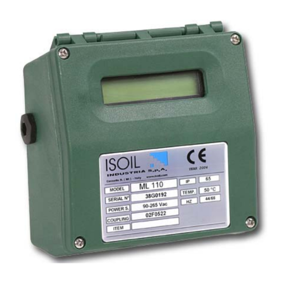
TECHNICAL CHARACTERISTICS ELECTRIC CHARACTERISTICS Classification of the converter: class I, IP65 for PA6 housing, IP67 for aluminum housing, installation category (overvoltage) III, rated pollution degree 2. Power supply Power supply Power supply Pmax versions voltage frequency current 100-240 V~ 44-66 Hz 5 VA 35 mA 18-45 V... -
Page 5: Dimensions (Pa6 Housing)
DIMENSIONS (PA6 HOUSING) COMPACT VERSION SEPARATE VERSION IF2 CAP COVER SCREW CABLE GLAND TORQUES To guarantee the housing’s IP degree the following torques are required: cover screws: 0,5 Nm cable glands: 4 Nm (in reference conditions) IF2 cap: 4 Nm 110_EN_IS_7_3_6X.doc... -
Page 6: Dimensions (Aluminum Housing)
DIMENSIONS (ALUMINUM HOUSING) COMPACT VERSION SEPARATE VERSION IF2 CAP COVER SCREW CABLE GLAND TORQUES To guarantee the housing’s IP degree the following torques are required: cover screws: 0,8 Nm cable glands: 1,8 Nm (in reference conditions) IF2 cap: 2 Nm 110_EN_IS_7_3_6X.doc... -
Page 7: Electrical Connections
ELECTRICAL CONNECTIONS GROUNDING INSTRUCTIONS ALWAYS ensure that the converter and the sensor are grounded (earthed) correctly. The grounding of the sensor and converter ensures that the equipment and liquid are equipotential. CONVERTER POWER SUPPLY ALUMINUM HOUSING PA6 HOUSING L (-) N(+) Before connecting the power supply, verify that the mains voltage are within the limits indicated on data plate (see also page 4). -
Page 8: Internal View Of Pa6 Converter
INTERNAL VIEW OF PA6 CONVERTER Power supply IF2 socket Signalling LED: See interpretation notes page 12 Keyboard Power supply PA6 CONVERTER TO SENSOR ELECTRICAL CONNECTIONS SEPARATE VERSION TERMINAL BLOCK COILS OUT2 OUT1 ALL SENSORS Sudden movements RS 485* INPUT 4-20mA ELECTRODES electrodes cable can cause noise during measurement... -
Page 9: Aluminum Converter To Sensor, Electrical Connections
INTERNAL VIEW OF THE ALUMINUM CONVERTER Power supply IF2 socket Signalling LED: See interpretation notes page 12 Keyboard Shield Power supply SENSOR cable ALUMINUM CONVERTER TO SENSOR, ELECTRICAL CONNECTIONS TERMINAL BLOCK M1 SEPARATE VERSION OUT2 OUT1 COILS ALL SENSORS Sudden movements of the electrodes cable can cause noise 4-20mA ELECTRODES... -
Page 10: Digital Input
DIGITAL INPUT External power supply Internal power supply 10 K 5 (+) 10 K 3/40 Vdc (ON) 0/1,5 Vdc (OFF) 6 (-) OPERATION ON INPUT ON/OFF Auto-calibration Tmin<T<1sec. = autocalibration T > 1 sec. = Auto zero AUTOCALIB. OFF Necessary conditions for enabling the function 3-40 V POS. -
Page 11: Output Wirings
OUTPUT WIRINGS Output on/off 1250 Hz Opto-insulated output with floating collector and 16 (out1) emitter terminals freely connectable 18 (out2) Maximum switching voltage: 40 Vdc Maximum switching current: 100 mA Maximum saturation voltage between collector and emitter @100 mA: 1,2 V Maximum switching frequency (load on the 43 V collector or emitter, RL=470 Ω, VOUT=24 Vdc):... - Page 12 DISPLAY FLAGS AND LED WARNING INTERPRETATION At ‘Power on’ of the converter, the user will see the following display screen. In the top right hand corner there may be a range of symbols. The symbols can be interpreted from the table below.
-
Page 13: Access To The Converter Keypad
ACCESS TO THE CONVERTER KEYPAD The keypad is accessible by loosening the 4 cover screws and opening the front cover of the converter. Three KEYS are set aside of the M3 power supply terminal block, allowing the user to change display visualizations and select functions. Ensure KEYPAD that the power supply cover is closed. -
Page 14: Accessing The Converter Functions At Start-Up (Power On)
ACCESSING THE CONVERTER FUNCTIONS AT START-UP (Power On) Example of visualized display pages at start-up The direct exposure of the converter to the solar rays, could damage the liquid crystals display. Note: The user will see the Active scale screen displayed (left) at power on of the converter. -
Page 15: Flow Rate Visualization
FLOW RATE VISUALIZATION The ML 110 permits to show a 5 digit character display for flow rate units. This mean the maximum flow rate value that can be represent on the display is 19999 (no matter the positioning of the decimal point) and the minimum is 0,025. -
Page 16: Converter Functions Setting Access Codes
CONVERTER FUNCTIONS SETTING ACCESS CODES User defined access codes Factory preset access codes The converter is delivered with the default Functions in the converter’s ‘Main menu’ are L2 (level 2) access code. The code if enabled by the access codes. The information required accessing ‘Main... - Page 17 EXAMPLE: “Quick start menu” function modification. Full scale value 1 (Fs1) from 4dm³/s to 5dm³/s. Enter in the “Quick start menu” The keypad button to be pressed at each step is indicated by the icon Access function “Fs1” symbol place on one of the three pressing the button indicated for less than 1 second keys of the keypad (here lower key)
- Page 18 EXAMPLE: “Main menu” function modification. Full scale value 1 (Fs1) from 4dm³/s to 5dm³/s. (Quick start menu enabled) Press the button indicated to enter the Main menu page screen from the Quick menu page Access to the “Main Menu” Enter in the “Quick start menu” pressing From start-up...
-
Page 19: Functions Menu
FUNCTIONS MENU The main menu is selected from the Quick start menu by pressing the key) and entering the factory code (11111). Functions denoted in grey are displayed only with other active functions, or with optional (for details of the functions with the symbol “*” refer to pages 22-27). modules. - Page 20 5.1* Total direct (positive) flow totalizers reset enable 5.2* Partial direct (positive) flow totalizers reset enable 5.3* Total reverse (negative) flow totalizers reset enable 5.4* Partial reverse (negative) flow totalizers reset enable 5.6 Totalise counting lock command (see page 10) 5.7* Autozero calibration external command 5.9 Range change external command 6.1* Output 1 functions (function info &...
- Page 21 10.1* Calibration of the converter (single occurrence each time function is selected) 10.2* Converter auto test (single occurrence each time function is selected) 10.3* Flow rate simulation enabling 11.1 Level 2 access code enter (user choice and setting of access code if required) 11.2 Load factory data pre-set 11.3...
-
Page 22: Functions Description
FUNCTIONS DESCRIPTION (description of the functions with access code< 3) Identification of the function (not visualized on display) MENU 1 - SENSOR (POS. 1) Nominal diameter of sensor [ND= XXXX] Converter request Menu visualized on the converter ( from 1 to 11) Synthetic description of the function The following pages give a description of the most important functions and how they can be changed or enabled/disabled by the user. - Page 23 Cubic inch Ounce Cubic centimeter American gallon Pound Milliliter British gallon Short tons Liter Cubic foot Cubic decimeter Standard barrel Decalitre Gram Oil barrel Hectolitre Kilogram Cubic yard Cubic meter KAmerican gallon KBritish gallon When a mass measure unit is set, the specific gravity function is automatically enabled by the system. Please, note that the mass measure is heavily affected by the temperature.
- Page 24 Secondly a variation form 10% to 100%, exceeding the acceleration threshold and then immediately sent to the output. Indeed there is always a minimum time between the measure acquisition and the outputs update. (POS. 3.3) Peak cut-off threshold [Peak thr=% XXX] Anomalous signal peak cut-off threshold set.
- Page 25 The NAMUR NE43 recommendations requires alarms signaling value for a current output lower than 3,6 mA (<18%) or greater than 21 mA (>105%). It is preferable to set the value of this function at 10%, so that the current value in cases of a.m. would be 2 mA, allowing the following diagnostics: current <...
- Page 26 (POS. 6.3) Duty cycle value for pulses/frequency output [Duty cycle=% XX] [OUT.1=XXXXXX] The duty cycle function defines the time ratio between ON and OFF state when frequency output is used: 50% means that the ON phase will equal that of the OFF phase, 60% means that the ON phase will be 60% and the OFF phase will be 40% of the total cycle time.
- Page 27 MENU 8 - DISPLAY (POS. 8.5) Totalizer modify enable [Tot.modif.=ON/OFF] Enable this function to modify the totalizer. From visualization pages, proceed in the following mode: 1) Push the key , set the L2 CODE if required (otherwise go to step 2) and then push the key 2) Positioning by the key to modify the numerical value push the key to access and then to...
-
Page 28: Alarm Messages, Causes And Corrective Actions
ALARM MESSAGES, CAUSES AND CORRECTIVE ACTIONS Messages ANOMALIES ACTION TO TAKE NO ALARMS All works regularly Check the maximum flow rate threshold set and MAX ALARM The flow rate is higher than the maximum threshold set the process conditions Check the minimum flow rate threshold set and MIN ALARM The flow rate is lower than the minimum threshold set the process conditions... - Page 29 110_EN_IS_7_3_6X.doc...
- Page 30 110_EN_IS_7_3_6X.doc...
-
Page 31: Conformity Declaration
CONFORMITY DECLARATION Isoil Industria spa Declares that the product: Converter model: ML 110 and sensor models MS 500 – MS 501 – MS 600 – MS 1000 – MS 2410- MS 2500 – MS 3700 – MS 3770 – MS 5000... - Page 32 110_EN_IS_7_3_6X.doc The version number of this manual is indicated by the fourth number from the right. The last three characters of the file name identify the software version to which this manual refers. The software version of the converter is visualized during it’s power up.
Need help?
Do you have a question about the ML 110 and is the answer not in the manual?
Questions and answers