Advertisement
Quick Links
To stay current on the accessories, applications, and software for the Radon
monitor, please visit Sun Nuclear's website, http://www.sunnuclear.com.
Professional Continuous
Professional Continuous
Professional Continuous
Professional Continuous
Radon Monitor
Model 1027
U.S. Patent #4,871,914
Document No. 102711C
November, 2000
Sun Nuclear Corporation
425A Pineda Court
Melbourne, FL 32940-7508
http://www.sunnuclear.com
e-mail: Mail@sunnuclear.com
telephone: 321-259-6862
fax: 321-259-7979
1 1 1 1
Advertisement

Related Manuals for Sun Nuclear 1027

Summary of Contents for Sun Nuclear 1027
- Page 1 Model 1027 U.S. Patent #4,871,914 Document No. 102711C November, 2000 To stay current on the accessories, applications, and software for the Radon monitor, please visit Sun Nuclear’s website, http://www.sunnuclear.com. Sun Nuclear Corporation 425A Pineda Court Melbourne, FL 32940-7508 http://www.sunnuclear.com e-mail: Mail@sunnuclear.com...
- Page 2 Using the data ports, you can print a complete report or download the data to a personal computer. The Model 1027 has been evaluated and accepted by the U.S Department of Environmental Protection (EPA).
- Page 3 Ambient room air, laden with radon, diffuses into the monitor’s detection chamber. Radon decay by-products emit alpha particles which are detected by the photodiode. At the end of the monitoring period, the results are available in any of three forms: numerical display on the control panel, printed report on the accessory printer, or computer display.
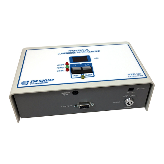
- Page 4 Controls Controls Controls Controls 11 12 Figure 1. Controls, displays, and connections PRINTER PORT: Only the Model 020030 portable printer can be con- nected to this port. The printer must be connected and powered-on before the information transfer is initiated. (See “Optional Portable Printer” on page 10.) 4 4 4 4...
- Page 5 DATA PORT: This RS-232 data port is designed to provide a means to transfer the information from the monitor to a personal computer. The information transferred is identical to that which is sent through the printer port. (For further information, see “Data Transfer to a Personal Computer”...
- Page 6 11 PRINT: (the YELLOW LED must be blinking) When this button is pressed, the monitor sends a report of the information contained in mem- ory to the both the PRINTER and DATA ports. When the button is pressed, the YELLOW LED will turn on. When released, the LED will turn off and the data is then transferred.
-
Page 7: Operation
Operation Operation Operation Operation Unpacking Unpacking Unpacking Unpacking Unpack the monitor. The package contains a monitor and key, a power adapter, the user’s manual, and a 3.5 inch floppy disk. NOTE: Save the packing material if you plan on returning the monitor for peri- odic re-calibrations. - Page 8 Clear command. To avoid a tamper notation on the first reading, be sure that you do not move or jar the monitor after the tamper sensor becomes active. In earlier models of the 1027, there were TILT and LEVEL indicators that illuminated during this 15-second period. The original TILT sensor has been replaced with a DISTURBANCE sensor which is more sensitive to movement.
- Page 9 NOTE: The AVG and CUR display values continue to update during the entire test, even if the test period exceeds the maximum storage of 90 intervals. The interval storage stops updating after 90 intervals until the next memory clear. Print Report Print Report Print Report Print Report...
- Page 10 Optional Portable Printer Optional Portable Printer Optional Portable Printer Optional Portable Printer Description Description Description Description The Model 020030 is a small, portable, dot-matrix impact printer (Figure 3). It uses an inked ribbon to generate the printed image. This allows the printer to utilize ordinary adding machine tape paper (2.25”...
- Page 11 3. Connect the printer power converter to the wall plug. 4. Connect the radon monitor power converter to the radon monitor. 5. Connect the radon monitor power converter into the wall plug. Figure 4. Connecting the printer Print Report Print Report Print Report Print Report 1.
- Page 12 Typical Printer Report Typical Printer Report Typical Printer Report Typical Printer Report Information to be written in by testing professional. “T” (tamper) Indicates move- ment occurred during this inter- val. The unit may have been tampered with. “P” (power) Indicates power interrupt during this interval.
- Page 13 1. Press down on the groove marks located on either side of the clear plastic window below the paper-tear bar (Figure 6). This will cause the back end of the panel to pop up. 2. Remove the panel exposing the ribbon cartridge. 3.
-
Page 14: Data Transfer To A Personal Computer
These cables are available from your local computer store. 2. Connect the cable from the Model 1027 Data Port to Com 2 or any unused RS-232 serial port on a standard IBM compatible PC or laptop (Figure 7). - Page 15 • apply headers, footers, dates, and serial numbers to reports, • annotate and edit reports, • store reports as text files, • store reports that can be imported into a spreadsheet. System Requirements System Requirements System Requirements System Requirements The software runs on any PC operating on Microsoft Windows 95, 98, ME, NT 4.0, or Windows 2000.
- Page 16 6. Click the Next button and follow the on-screen directions. 7. When the installation is complete, click the Finish button. The installation screen will close. In Windows 95 and higher, the Radon 1027 icon will appear on the desktop. Starting the Software...
- Page 17 Menu bar Editing area Message area Figure 11. Program opens with a blank screen Com Port Setup Com Port Setup Com Port Setup Com Port Setup Most PCs have at least two Com Ports (serial communications ports), identi- fied as Com Port 1 and Com Port 2, with connectors located at the back of the computer.
- Page 18 • Monitor S/Ns—enter the serial number for each of the Model 1027 radon monitors you are using, and press the down arrow. This inserts the numbers in the list below. Prior to transferring a report to your PC, double-click the serial number you want to appear in the Radon Mon- itor S/N box.
- Page 19 4. Click on Get Data on the menu. The message at the bottom of the screen will say “Listening for data on Com 1...” 5. Hold down both buttons on top of the Model 1027 until the yellow LED comes on continuously. Then release both buttons. The yellow LED will now be flashing.
- Page 20 7. The Model 1027 report will appear on the computer screen (Figure 15). Figure 15. Report displayed in the editing screen 8. Use the scroll bars at the right side and bottom to view other parts of the report. Editing and Printing Reports...
- Page 21 If your line power is different from 120 VAC, 60 Hz you may use locally avail- able AC line adapters that conform to the following specifications: Radon Monitor Model 1027 Input Power Specification: • 9-12 VDC or VAC, 200 mA minimum •...
-
Page 22: User Maintenance
The “Power to Printer” output supplies 10 VAC at 1 amp continuous, 3 amps peak. The “Power to Unit” output is 5-25 VDC adjustable at 7 watts or 1 amp. The internal adjustment is factory-set to approximately 18.2 VDC for use with the Sun Nuclear Model 1027 Radon Monitor. User Maintenance User Maintenance... - Page 23 CURRENT value. However the AVERAGE is main- value tained until it is deliberately CLEARED. For more help, see Sun Nuclear Corporation’s web site for Product FAQs, information, and bulletin board: http://www.sunnuclear.com. Changing the Backup Battery Changing the Backup Battery...
- Page 24 WARNING: The unit contains high-voltage circuits. Do not open the case. There are no user-serviceable parts inside the unit. For service or calibration, return the unit to Sun Nuclear Corporation as instructed in the Warranty statement on the inside back cover.
Need help?
Do you have a question about the 1027 and is the answer not in the manual?
Questions and answers