Advertisement
Quick Links
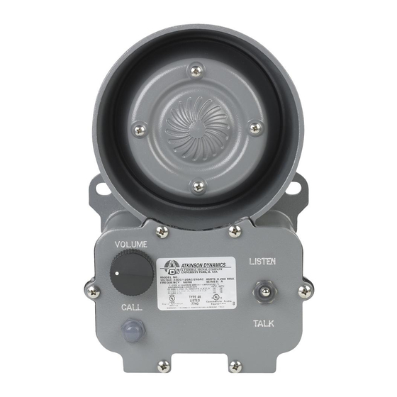
AD-26, AD-27, AD-56, and AD-57
Atkinson Dynamics Wall Mount Intercoms
Installation and Maintenance Manual
2645 Federal Signal Drive
University Park, IL 60484-3167
Customer Support +1-708-534-4756, iordersup@fedsig.com
Technical Support 1-800-755-7621+1-708-587-3587, signalsupport@fedsig.com
www.fedsig.com
2561494
Rev. H2 620
Printed in U.S.A.
© 2020 Federal Signal Corporation
Advertisement

Summary of Contents for Federal Signal Corporation Atkinson Dynamics AD-26
- Page 1 AD-26, AD-27, AD-56, and AD-57 Atkinson Dynamics Wall Mount Intercoms Installation and Maintenance Manual 2645 Federal Signal Drive University Park, IL 60484-3167 Customer Support +1-708-534-4756, iordersup@fedsig.com Technical Support 1-800-755-7621+1-708-587-3587, signalsupport@fedsig.com www.fedsig.com 2561494 Rev. H2 620 Printed in U.S.A. © 2020 Federal Signal Corporation...
- Page 2 INSTALLATION AND SERVICE INSTRUCTIONS FOR ATKINSON DYNAMICS HEAVY-DUTY INTERCOMS SAFETY MESSAGE TO INSTALLERS, USERS AND MAINTENANCE PERSONNEL It is important to follow all instructions shipped with this product. This device is to be installed by a trained electrician who is thoroughly familiar with the National Electrical Code and will follow NEC Guidelines as well as local codes.
-
Page 3: Call Button
Additional Model Information Letter Group Function/Feature “A” Call button “C” Primary mode “D” Secondary mode Number Group “‑1” Remote power “‑2” Provisions for external talk/listen switch (foot pedal ready) “‑3” External call contacts for auxiliary signal “‑4” Extreme temperature use (‑50 °F to 150 °F) “‑6”... -
Page 4: External-Power-Source
HEADSET MICROPHONE WITH-BELT-SWITCH: The “M34” Headset Microphones and Belt Switches are an additional option for environments with a high level of ambient noise. Keying the belt switch overrides the default mode of the intercom and enables audio transmission to all Primary units in the intercom system. - Page 5 B. Unpacking the Intercom After unpacking the Atkinson Dynamics Intercom, examine it for damage that may have occurred in transit. If the equipment has been damaged, do not attempt to install or operate it, and file a claim immediately with the carrier stating the extent of the damage.
- Page 6 Optional: A 1K, 1W resistor is included in a kit with each intercom. Installing the resistor across the audio lines helps to reduce noise in certain environments. Only one resistor needs to be installed on the lines for any system installation. See Figures 1 through 19 starting on page 7 for typical intercom connections and wiring information.
- Page 7 G. Warranty. Atkinson Dynamics guarantees their intercoms to be free of defects at the time of delivery. If damage is found to be a factory defect, Atkinson Dynamics will warrant all labor charges for repair for one full year, and all replacement parts for two full years.
- Page 13 POWER CONNECTIONS: NOTES +DC Power 12/24V models 1. Speaker/Microphone 120/240V models 2. Off/On Speaker Volume Common 12/24V models Control Neutral 120/240V models 3. Talk/Listen Switch Earth Ground 120/240V models only 4. Remote Secondary Station Model AD‑SV‑25 REMOTE SECONDARY STATION Operating Principle: 1.
- Page 14 SPEAKER BLK 1 WHT 2 PRIMARY 200 FT. MAX. AUDIO COMMON 1WATT SEE POWER CONNECTIONS 290A3743B Operating Principle: 1. Secondary station is both a speaker and a microphone. 2. Primary is normally in “Listen” mode until the talk button is pressed to talk to remote. 3.
- Page 19 PRIMARY SPEAKER GRN 1 WHT 2 CONTROL SECONDARY 200 FT. MAX. AUDIO COMMON PRIMARY SPEAKER 1WATT SEE POWER CONNECTIONS 290A4068 OPERATING PRINCIPLE: 1. Primary station is both a speaker and a microphone. 2. Primary is normally in “Listen” mode until the PTT (press‑to‑talk) switch is pressed to talk to Secondary.
- Page 27 3.88 5.68 Δ 2 HOLES 9.88 4.84 5.00 6.50 290A3697...
- Page 28 Atkinson Dynamics 2645 Federal Signal Drive, University Park, Illinois 60484 Customer Support 1-800-344-4634+1-708-534-4756, iordersup@fedsig.com Technical Support 1-800-755-7621+1-708-587-3587, signalsupport@fedsig.com www.fedsig.com © 2020 Federal Signal Corporation. 2561494 Rev. H2 0620 Printed in U.S.A.
Need help?
Do you have a question about the Atkinson Dynamics AD-26 and is the answer not in the manual?
Questions and answers