Table of Contents
Advertisement
Quick Links
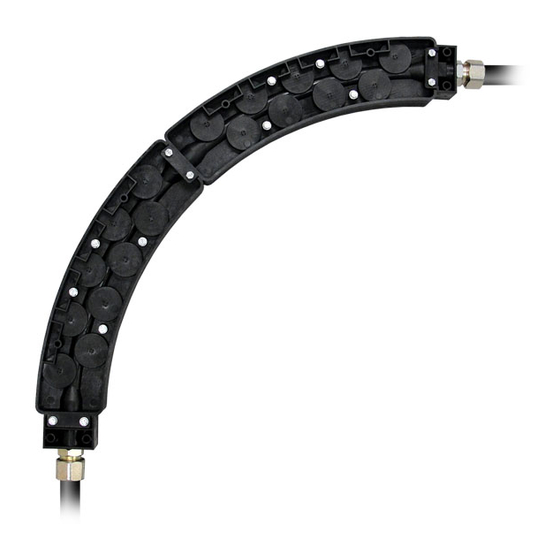
LARGE GUIDE MODULE ASSEMBLY INSTRUCTIONS
Tools Required:
(2) 8mm wrenches
(1) Rotary tool with stone bit
(to round wire end prior to feeding)
Assembly of 90°, 135° and 180° Guide Modules
Step 1: Connecting Modules
Insert intermediate pin in one end of
module until it firmly seats (Step 1-A).
Connect the two modules using the
intermediate pin and ears to align
the modules together (Step 1-B). Use
the
intermediate
fasteners
lock modules together. Continue
connecting modules until you have
created the proper bend radius.
Step 2: Connecting End Caps
Insert one end cap pilot pin into the
end of the joined module(s). This will
guide the wire into the module wire
track. Connect the appropriate end
cap over the end cap pin. The pin
will stick out approx. 1/4" (6.3mm).
Insert and tighten the end cap
fasteners to lock in place.
Repeat with the other end cap. This
is the wire exit point where wire will
be
guided
into
the
Connect the appropriate end cap
over the pin and use end cap
fasteners to lock in place.
Step 3: End Cap Fitting Options
Pass Through Compression Fitting (recommended): Thread the pass-through compression
fitting (A-9) into the appropriate end cap, making sure to correctly follow the wire path
designated with the end cap pin. Deburr and countersink the conduit out to the conduit
edge. Push the conduit through the compression nut until the conduit bottoms out on the
end cap pin. Tighten compression nut. Doing so will pull the conduit to the face of the end
cap pin without crushing the conduit.
Quick Disconnect Option: Attach A-5HD quick disconnect into the appropriate end cap.
The pilot pin fits in the interior of the disconnect. Optional U-005 orange insulator sleeve
shown in photo not included.
WGM-LW-1 Kit Contents:
(1) 45° module
(2) Intermediate fasteners
(1) Intermediate pilot pin
to
STEP 1-A
Insert Fasteners
STEP 1-B
END CAP A
conduit.
STEP 2
End Cap Kit
(1) "A" style end cap with threaded insert
(1) "B" style end cap with threaded insert
(4) End cap fasteners
(2) End cap pilot pins
Intermediate
End Cap
Always deburr/
countersink
conduit ends
with a stone bit
(517) 782-8040 • Fax (517) 782-8039 • Jackson, MI 49201 USA
(WGM-ECK-LW-50)
Pin
90° GUIDE MODULE
WIRE GUIDE MODULE &
END CAP ASSEMBLIES
B
STEP 3: Compression Fitting
STEP 3: Quick Disconnect
www.wire-wizard.com
Contents:
End
Pilot Pin
Cap A
45° GUIDE
MODULE
Last Revised: 6/22/17
Advertisement
Table of Contents

Summary of Contents for Wire wizard GUIDE MODULE XL
- Page 1 LARGE GUIDE MODULE ASSEMBLY INSTRUCTIONS Tools Required: WGM-LW-1 Kit Contents: End Cap Kit Contents: (WGM-ECK-LW-50) (2) 8mm wrenches (1) 45° module (1) “A” style end cap with threaded insert (1) Rotary tool with stone bit (2) Intermediate fasteners (1) “B” style end cap with threaded insert (to round wire end prior to feeding) (1) Intermediate pilot pin (4) End cap fasteners...
- Page 2 ASSEMBLY & MAINTENANCE FEEDING WIRE: It is beneficial to round the wire end upon initial feeding. Use a stone bit with a rotary tool to deburr any sharp edges from the wire end. This will prevent unnecessary hang-ups when feeding the wire to the feeder. MAINTENANCE: Wire Guide Modules should be cleaned periodically.
Need help?
Do you have a question about the GUIDE MODULE XL and is the answer not in the manual?
Questions and answers