Table of Contents
Advertisement
Quick Links
Advertisement
Table of Contents

Summary of Contents for Forza SNMP
- Page 1 SNMP network management card and monitoring software User and installation manual...
- Page 2 The integrated Shutdown Wizard does not only prevent data loss from power outages by safely shutting down UPS units, but also stores programming data and scheduled power off times. All UPS warnings and fault event records can be kept in the SNMP web...
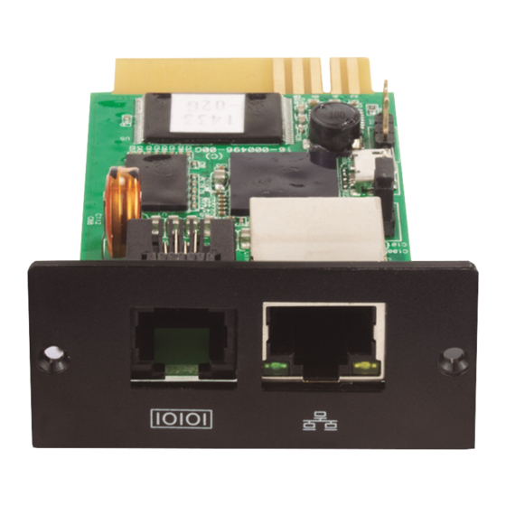
- Page 3 Step 3: Plug a user-supplied ethernet cable to the ethernet port (RJ-45) on the SNMP web manager. Ethernet Step 4: Use a RJ-11 cable to connect the sensor port on the SNMP web manager to an optional environmental monitoring device, if adding one in your installation.
-
Page 4: System Requirements
Step 3: After clicking install, the progress bar will be displayed, as illustrated below. 2.3 System requirements 1 GB physical memory at least (2 GB is recommended) 2 GB hard disk space at least Administrator authority is required A display with more than 16-bit colors and a resolution of over 800 x 600 is recommended TCP/IP protocol must be installed for network management Platforms supported by software are listed below: Windows 2000... - Page 5 Step 6: Click on the Choose button to change the default folder, if desired. After selecting the destination folder, click Next Note: If during the installation ViewPower Pro detects that an earlier version of the software is present, users will be as illustrated below.
-
Page 6: Snmp Manager
SNMP status This section displays the SNMP status, 0 or 1, after selecting an IP from the corresponding list. If there is a program inside the selected SNMP card, the status becomes 1; otherwise 0 will be displayed. If no IP address is selected, then “---“ will be shown as default. - Page 7 Use system time When the Use system time option is selected, the SNMP card will automatically apply the PC system time. See illustration below: Step 2: Check the SNMP reset enable box to now enable the Reset button.
-
Page 8: Online Upgrade
Step 1: select the FTP server IP address as seen in the illustration included above. NOTE: If upgrading the SNMP Web Server in the LAN, the FTP server IP address will be the IP address of the current PC in the LAN. -
Page 9: System Management
Step 4: When the update is complete, you may check the message in the output window. Part A: You can set the SNMP protocol version for the selected or all the devices. Simply choose the SNMP protocol version first. The default setting is V2. If choosing V3, the encryption of data packets must be set. Select devices to apply this setting. -
Page 10: System Configuration
NOTE: The password must be between 8 ~ 15 characters in length. If this change is applied to all SNMP devices, then the same 4. System configuration password must be consistently used to access each of them. Static trap address It is possible to configure two static addresses and change the port through the SNMP Manager. -
Page 11: Software Upgrades
Import Certificate: it will import a HTTPS certificate from a third party. It supports JKS and PCKS12 types of certificate as 4.3 ViewPower Pro Start and Exit Setting shown in the dialog box below. Refer to section C in the illustration included in section 4 for a detailed configuration of the ViewPower Pro start and exit setting: Server startup type: If Automatic is selected, the software will automatically start up when the PC is turned on. - Page 12 Manual update A. Function menu It offers a complete set of tools designed for navigation and for setting the GUI. Users can manually update the software, as detailed below: B. Login section 1.Click on Manually Update from the dropdown menu. It shows the type of the currently logged-in user.
- Page 13 Step 2 Enter the old password and type twice the new one. (The password should be at least 6 characters in length). Then click the Apply button to successfully modify password for the administrator. NOTE 1: Simply click the Login button on the top right corner to sign in to the software. NOTE 2: Should the user forget the password, it will be necessary to reinstall the software.
-
Page 14: Load Configuration
1. Select Configuration >> SMS, as in the illustration below: 1. Enter the SMTP server, SMTP port, Send from Email address, User name and password. Check the box next to password if authentication is required. If an Exchange Server is used as the mailbox system, it is required to configure its domain name in the SMTP sever field and check the corresponding box. -
Page 15: Event Action
Enter the IP address of the computer being used, followed by its MAC address. The MAC address can be obtained by selecting Event record: when and event occurs, it will save the event records in the database. the Auto match button as long as there is active connection in the system. Audible alarm: when an event occurs, then the selected media file will be played. -
Page 16: Schedule Tasks
6.10 Modbus communication setting This page displays all connected PCs through the ModBus interface. Step 1: Select Configuration>> ModBus Communication Setting Text Message: contains a description of the event assigned to the selected dry-contact sensor. Default dry-contact: defines the dry-contact sensor number to which a specific monitoring event is assigned. There are five selections: none, 1, 2, 3 and 4. - Page 17 Step 2: Set the frequency and time on the right column. NOTE: Please be aware of the following rules when setting the schedule. Once – power-off time should be earlier than power-on time. Daily schedule – power-off time should be earlier than power-on time. Power-on and power-off times should be set on the same day.
- Page 18 Graphic view: Each UPS is represented by an icon. It shows the icon on a background picture. To avoid mistakes, it has a security function, whereby only administrators are permitted to “unlock” such icons and be able to drag and drop them at will. These icons are set to lock by default Refer to the illustrations below.
-
Page 19: Basic Information
In this window, the monitored UPS information is shown in real time, such as battery, load, input and output values. Select Status followed by the Environmental information tab. Note: This information is available only when the SNMP card is connected to an Environmental monitoring device (EMD). Diagram Select Status followed by the Diagram tab. -
Page 20: Parameters Setting
Battery number settings: It is used to set the number of batteries connected in parallel. 7.3 Parameters setting Voltage and frequency range for bypass mode: It is used to set acceptable voltage and frequency range to operate in Some UPS functions can be set and modified via software. Parameter settings include backup time for programmable outlets bypass mode. - Page 21 Event statistics It provides an statistics of all the events that have taken place in the UPS units that have the program installed, within a time range between points A and B, and the resulting change percentage [= 100*(B/A – 1)%]. Note: This window lists bypass, battery, software, load, input, parallel system, communication and UPS internal events.
- Page 22 Step 1: Select View >> History >> Data, as shown in this window. EMD logs This section will exhibit environmental information detected by the EMD during the selected time period. It includes input and output voltages, frequency, load level, battery capacity and the UPS temperature. Step 1: Select View >>...
- Page 23 11.2 SNMP web pro GUI The SNMP web card GUI includes the function menu, the login interface and main screen. Refer to the illustration below. 11. SNMP web pro From the service tray utility open the SNMP Manager to access the graphical user interface through the web.
-
Page 24: Ups Settings
11.3 Function menu 11.3.2 UPS settings 11.3.1 Information Parameter settings Status Some UPS functions can be set and modified via software. Parameter settings include backup time for programmable outlets (P1), battery number settings, voltage and frequency range settings for bypass mode in addition to voltage range settings for Select Information>Status. - Page 25 Web user It enables the operator to access the SNMP web pro. Enter the user name and password in the corresponding fields. By default, access to settings is not restricted. HTTP and HHTPS modification can also be performed. The default setting is 80 for HTTP and 443 for HTTPS.
- Page 26 Configure the baud rate of the GSM modem at 9600. Next, use a RJ-11 to DB9 cable to connect the data transmission port (2) of the SNMP web card to the modem. After entering the MAC addresses of the remote PCs into the corresponding fields, the user will be able to control the PCs remotely.
- Page 27 The UPS will be disconnected only after the system is turned off completely. Users can choose to The following window is used to configure time zones and daylight savings time settings for the SNMP. shut down the system without shutting down the UPS.
- Page 28 It can save up to 200,000 threads without experiencing any data loss, even if there is a power failure. Use this page to set the SNMP web card basic information such as IP address, password, trap IP address, SNMP UDP port and Select Log >...
- Page 29 Open a web browser and enter http://xxx.xxx.xxx.xxx:15178/VPMobile, as shown below: 11.3.6 Help Serial port debug Use this port to test communication status between the SNMP card and the device. Select Help and click on the Serial Port 12.2 ViewPower pro GUI Debug option to access this page.
- Page 30 2. Shortcut menu 4. Basic information When the UPS ID is selected, the shortcut menu will be displayed to provide quick links to the status, basic information, This screen displays basic data about the UPS and batteries, in addition to the rated values and purchasing details pertaining parameters setting and real-time control pages.
- Page 31 6. Parameter setting 7. Real time control 1. Select the functions by clicking Enable or Disable. Use the arrows to modify the values or enter the numbers directly in UPS turn On/Off: Connects or disconnects the UPS. the fields. Battery self-test: The unit provides three types of battery self-tests: 2.
- Page 32 NOTES NOTES...
Need help?
Do you have a question about the SNMP and is the answer not in the manual?
Questions and answers