Table of Contents
Advertisement
Quick Links
Installation of the PWT MICROPlumb® MCR 4014, MCR 8012 and MCR-8013 Series Controller incorporates the latest advances in microprocessor technology to provide maximum control of your plumbing
system. MICROPlumb® patented sensing and metering products can be programmed to do just about anything you require, when you require it, including the ability to Delay and Lock-Out fixture activation.
MICROPlumb products control showers, water closets, lavatories and combination fixtures and help maintain operation of ON/OFF/DELAY. These modular, flexible systems for new constructions, retrofit or
expansion applications have few moving parts, no mechanical metering devices, and operate on low voltage to ensure safety and reliability. The following instructions will serve as a guide when installing the MCR
4000 and MCR 8000 Series Controllers. As always, good safety practices and care are recommended when installing your new controller.
Unless otherwise noted, Sloan Valve Company warrants its products, manufactured and sold for commercial or industrial uses, to be free from defects of material and workmanship for a
period of three (3) years (one year for SF faucets, special finish and PWT electronics and 30 days on PWT software) from the date of first purchase. During this period, Sloan Valve Company
will, at its option, repair, replace, or refund the purchase price of any produce which fails to conform with this warranty under normal use and service. This shall be the sole and exclusive
remedy under this warranty. Products must be returned to Sloan Valve Company, at customer's cost. No claims will be be allowed for labor, transportation or other costs. This warranty
extends only to persons or organizations that purchase Sloan Valve Company's products directly from Sloan Valve Company for purpose of resale.
THERE ARE NO WARRANTIES WHICH EXTEND BEYOND THE DESCRIPTION ON THE FACE HEREOF. IN NO EVENT IS SLOAN VALVE COMPANY RESPONSIBLE FOR ANY
CONSEQUENTIAL DAMAGES OF ANY MEASURE WHATSOEVER.
Prior to Installation
PRIOR TO INSTALLATION
Before you install the MCR series controller, be sure the items listed below are installed.
• 24 VAC step down transformer • Push buttons • Flushometer • Lavatory/Shower solenoids
IMPORTANT
• ALL PLUMBING SHOULD BE INSTALLED IN ACCORDANCE WITH APPLICABLE CODES AND REGULATIONS.
• WATER SUPPLY LINES MUST BE SIZED TO PROVIDE AN ADEQUATE VOLUME OF WATER FOR EACH FIXTURE.
• FLUSH ALL WATER LINES PRIOR TO MAKING CONNECTIONS.
• ALL ELECTRICAL WIRING IS TO BE INSTALLED IN ACCORDANCE WITH NATIONAL/LOCAL CODES AND REGULATIONS.
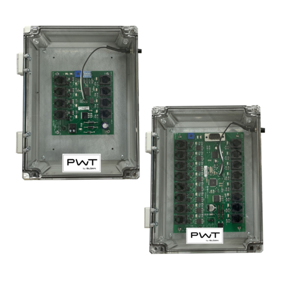
MCR 4014, MCR 8012 CONTROLLERS
INSTALLATION AND PROGRAMING INSTRUCTIONS
LIMITED WARRANTY
MCR 4014, MCR 8012 CONTROLLERS
INSTALLATION AND PROGRAMING
INSTRUCTIONS
1
CODE NO. 0816865
Rev.1 (08/19)
Advertisement
Table of Contents

Subscribe to Our Youtube Channel
Summary of Contents for Sloan PWT MCR 4014
- Page 1 Unless otherwise noted, Sloan Valve Company warrants its products, manufactured and sold for commercial or industrial uses, to be free from defects of material and workmanship for a period of three (3) years (one year for SF faucets, special finish and PWT electronics and 30 days on PWT software) from the date of first purchase. During this period, Sloan Valve Company will, at its option, repair, replace, or refund the purchase price of any produce which fails to conform with this warranty under normal use and service.
- Page 2 1. Mount Controller 1. Loosen the polycarbonate screws. 2. Open polycarbonate cover in front of controller. 3. Install controller so that all cables enter from the bottom. Controller must be located within 200 ft. from furthest push button and within 200 ft. of power supply transformer. 4.
- Page 3 4. Adjusting the Potentiometer 1. Turn on power to controller. 2. Wait for LED 17 and LED 18 to stop flashing. 3. Turn potentiometer to maximum counterclockwise setting. This is zero position. 4. Slowly turn potentiometer clockwise. Count the number of times that LED 18 flashes. Each flash relates to a time increment that increases either a runtime or lockout time.
- Page 4 SOLUTION: Shut off water to the valve. Remove top cap and inside cover. Replace inside cover (A-71). Reassemble. SLOAN • 10500 SEYMOUR AVENUE • FRANKLIN PARK, IL 60131 Phone: 1-800-982-5839 or 1-847-671-4300 • Fax: 1-800-447-8329 or 1-847-671-4380 • sloan.com 0816865 Copyright © 2019 Sloan Valve Company PWT MCR-4014-AL/MCR 8012-AX I.I.
Need help?
Do you have a question about the PWT MCR 4014 and is the answer not in the manual?
Questions and answers