Table of Contents
Advertisement
Quick Links
Advertisement
Table of Contents

Related Manuals for THORLABS NanoRotator

Summary of Contents for THORLABS NanoRotator
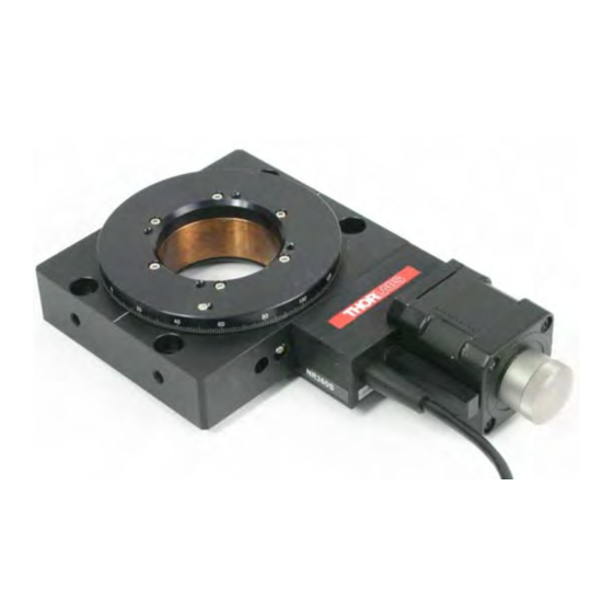
- Page 1 NR360S Motorized 360° Rotation Stage User Guide Original Instructions...
-
Page 2: Table Of Contents
1.2 General Warnings ...................3 Chapter 2 Overview ..................4 2.1 Description ....................4 2.2 Accessories .....................5 Chapter 3 Operation ..................6 3.1 Using the Nanorotator with the APT System ..........6 3.1.1 Background ......................6 3.1.2 System Setup ..................... 7 Chapter 4 Installation ..................8 4.1 Unpacking ....................8 4.2 Transportation ..................8... -
Page 3: Chapter 1 Safety
Chapter 1 Safety 1.1 Safety Information For the continuing safety of the operators of this equipment, and the protection of the equipment itself, the operator should take note of the Warnings, Cautions and Notes throughout this handbook and, where visible, on the product itself. The following safety symbols may be used throughout the handbook and on the equipment itself. -
Page 4: Chapter 2 Overview
66 turns of the stepper motor. An electrical limit switch has been fitted to allow the user to datum the Nanorotator but this limit switch is only active in the negative direction. This means that the Nanorotator will run to infinity in the positive direction, but will not pass zero in the negative direction. -
Page 5: Accessories
NR360S Motorized 360° Rotation Stage 2.2 Accessories Several mounting plates are available which allow the stage to be fixed to an optical table in either horizontal or vertical configurations. The adapter plates allow device holders to be fitted to the rotating platform. The stage can also be mounted onto one of our NST or TravelMax long travel stages. -
Page 6: Chapter 3 Operation
Nanorotator, or both. Manual control of the Nanorotator can be achieved by switching off the drive to the motors. Please refer to the relevent controller manual. Caution The electrical limit switch does not operate when the motor is being turned by hand. - Page 7 Selecting an incompatible stage type could result in reduced velocity and resolution. 7) In the ‘Stage’ field, select ‘HS NanoRotator’ from the list displayed. 8) Click the 'Add Stage Association' button. 9) A default configuration is set at the factory and stored in the non-volatile memory of the motor controller.
-
Page 8: Chapter 4 Installation
The unit should only be handled by its base, not by the top platform or any attachments to the top platform. Do not carry the Nanorotator by the drive actuator. Serious damage may occur if excessive force is applied to the drive. -
Page 9: Attaching To A Work Surface
NR360S Motorized 360° Rotation Stage 4.4 Attaching to a Work Surface Several mounting plates are available which allow the stage to be fixed to an optical table in either horizontal or vertical configurations. The adapter plates allow device holders to be fitted to the rotating platform. The stage can also be mounted onto one of our NRT or LNR series long travel stages. -
Page 10: Dimensions
4.6 Dimensions 4.6.1 NanoRotator Dimensions 42.2 (1.66) SQUARE 50.0 (1.97) 2 HOLES M6 ON 3 SIDES 34.5 (0.32) 50.5 (1.99) 50.5 (1.99) (1.36) 115.5 (4.55) 50.0 (1.97) all dimensions in millimetres (inches) Fig. 4.1 NanoRotator dimensions HA0040T Rev 10 Mar 2016... -
Page 11: Lnr Or Nrt Stage Mounting Plate
NR360S Motorized 360° Rotation Stage 4.6.2 Table Mounting Plate all dimensions in millimetres (inches) 114.0 (4.49) 10.0 (0.39) 101.0 (3.98) 6.5 (0.26) 4 HOLES 8.0 (0.32) THROUGH Fig. 4.2 Table mounting plate dimensions 4.6.3 LNR or NRT Stage Mounting Plate all dimensions in millimtres (inches) 4 HOLES Ø7.50 (0.3) THROUGH AND C/BORED TO Ø11.50 x7.0 (Ø0.45 x 0.28) DEEP... -
Page 12: Vertical Mounting Bracket
Chapter 4 4.6.4 Vertical Mounting bracket all dimensions in millimetres (inches) 112.0 (4.41) 50.5 (1.99) Ø68.0 (2.68) APERTURE › 92.0 (3.62) 4 HOLES M6 (1/4"-20 UNC) THROUGH 7 HOLES Ø7.00 (0.28) THROUGH C/BORED Ø11.0 (0.43) X 6.5 (0.26) DEEP IN TOP FACE Fig. -
Page 13: General Purpose Carriage Plate
(0.12 +0.002 WIDE X 0.07 DEEP) 14 HOLES M3 (6-32 UNC) THROUGH 13.25 (0.52) 13.25 (0.52) PLATE 5.0 (0.2) THICK Fig. 4.5 Grooved carriage plate Other mounting and adpter plates are available, please see Chapter 6 and www.thorlabs.com for more details. -
Page 14: Chapter 5 Specification
Chapter 5 Specification Parameter Value General Specifications Construction Aluminum Body and Platform with Black Finish Travel 360° Continuous Rotation On Axis Load Capacity* 110 lbs (50 kg) Drive Mechanism Worm Drive Gear Ratio 66:1 Limit Switches Mechanical, Normally Open Reference Signal Every 360° Motor Type 2 Phase Stepper Accuracy... -
Page 15: Chapter 6 Parts List
Chapter 6 Parts List Description Part Number Table Mounting Plate (Imperial) NR360SP1 Table Mounting Plate (Metric) NR360SP1/M Vertical Mounting Bracket (Imperial NR360SP2 Vertical Mounting Bracket (Metric) NR360SP2/M Grooved Purpose Carriage Plate NR360SP4 (Imperial Grooved Purpose Carriage Plate (Metric) NR360SP4/M Mounting Plate to NST or LNR (Imperial) NR360SP5 Mounting Plate to NST or LNR (Metric) NR360SP5/M... -
Page 16: Chapter 7 Regulatory
Chapter 7 Regulatory 7.1 Declarations Of Conformity 7.1.1 For Customers in Europe See Section 7.3. 7.1.2 For Customers In The USA This equipment has been tested and found to comply with the limits for a Class A digital device, persuant to part 15 of the FCC rules. These limits are designed to provide reasonable protection against harmful interference when the equipment is operated in a commercial environment. -
Page 17: Waste Treatment On Your Own Responsibility
• left over parts of units disassembled by the user (PCB's, housings etc.). If you wish to return a unit for waste recovery, please contact Thorlabs or your nearest dealer for further information. 7.2.2 Waste treatment on your own responsibility If you do not return an "end of life"... -
Page 18: Ce Certificate
Chapter 7 7.3 CE Certificate HA0040T Rev 10 Mar 2016... -
Page 19: Chapter 8 Thorlabs Worldwide Contacts
Chapter 8 Thorlabs Worldwide Contacts USA, Canada, and South America Scandinavia Thorlabs, Inc. Thorlabs Sweden AB 56 Sparta Ave Bergfotsgatan 7 Newton, NJ 07860 431 35 Mölndal Sweden Tel: 973-579-7227 Tel: +46-31-733-30-00 Fax: 973-300-3600 www.thorlabs.com Fax: +46-31-703-40-45 www.thorlabs.us (West Coast) www.thorlabs.de... - Page 20 Thorlabs Inc. Thorlabs Ltd. 56 Sparta Ave 1 Saint Thomas Place, Ely Newton, NJ07860 Cambridgeshire CB7 4EX, Tel: +1 973 579 7227 Tel: +44 (0) 1353 654440 Fax: +1 973 300 3600 Fax: +44 (0) 1353 654444 www.thorlabs.com www.thorlabs.com...
Need help?
Do you have a question about the NanoRotator and is the answer not in the manual?
Questions and answers