
Related Manuals for Rigol RPL1116

Summary of Contents for Rigol RPL1116
- Page 1 RIGOL User’s Guide RPL1116 RPL1116 Active Logic Probe © 2013 RIGOL Technologies, Inc. All Rights Reserved.
-
Page 2: General Safety Summary
General Safety Summary Connect and disconnect the probe properly. Observe all terminals ratings. Do not touch exposed connections and components after power on. Do not operate with suspected failures. Do not operate without covers. Do not operate in an explosive atmosphere. Do not operate in wet conditions. -
Page 3: Product Overview
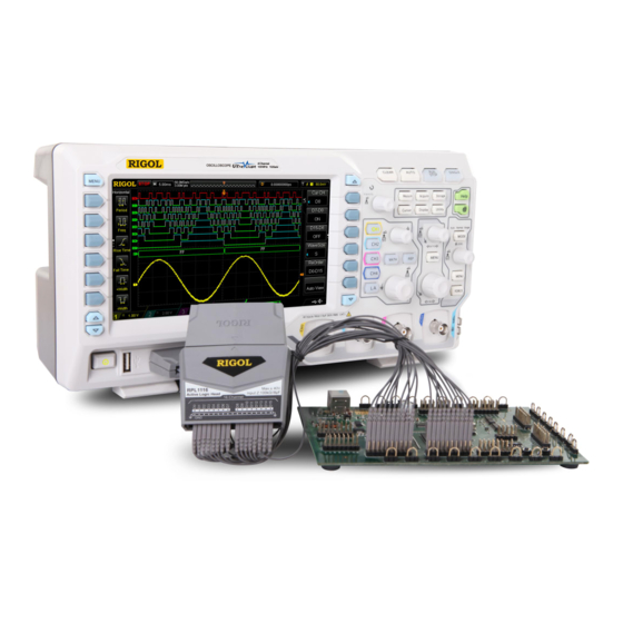
The 16 digital channels (D0-D15) of RPL1116 are divided into two channel groups (D0-D7 and D8-D15) each of which includes signal interfaces and ground interfaces. All the channels are marked with different numbers on the label of the probe head to identify different channels. - Page 4 The Using Method of the Logic Probe 1. Connect RPL1116 to the oscilloscope: connect the active logic head to the main cable input, and then connect the main cable output to the digital signal input terminal at the front panel of the oscilloscope as shown in the figure below.
- Page 5 2. Connect the signals under test to RPL1116: users can connect any number (≤16) of the signals under test to RPL1116 according to the test need. Note that the amplitude of the input signal should not exceed the maximum working voltage range of the probe. RPL1116 provides two connection methods to realize convenient and flexible detection.
- Page 6 shown in Figure 2. Figure 1 Figure 2 3. Set the probe: press LA at the front panel of the oscilloscope to enter the probe setting menu. Users can view and set the following parameters under this menu: threshold level (the threshold levels of D0-D7 and D8-D15 can be adjusted independently), waveform size (applicable to all the channels;...
- Page 7 LA menu and please disconnect all the connections to the RPL1116 input terminal during the calibration. 4. Function Check: after finishing the above operations, the signal under test will be displayed on the corresponding digital channel on the oscilloscope screen.
-
Page 8: Probe Specifications
Probe Specifications Input channels Threshold range ±15 V Threshold accuracy ±100m V+3% of threshold setting Max input voltage ±40 V Max input dynamic range ±10 V + threshold setting Min voltage swing 500 mV Min detectable pulse width 10 ns Input impedance 100 kΩ±2% Input capacitance... - Page 9 Accessories Item Description Quantity Main Cable Active Logic Head Lead 32 (2×16) Grabber Chinese and English User’s Guide RPL1116 Packing Box - 8 -...
- Page 10 Accessories Sketch Map Main Cable Active Logic Head Lead Grabber - 9 -...
- Page 11 Contact Us If you have any problem or requirement when using our products or this manual, please contact RIGOL Technologies, Inc. E-mail:service@rigol.com Website:www.rigol.com UGE26X02-1110 Aug. 2014 ZN1 0 2 0 0 0 2 6 5 9 - 10 -...
Need help?
Do you have a question about the RPL1116 and is the answer not in the manual?
Questions and answers