Table of Contents
Advertisement
Quick Links
Advertisement
Table of Contents

Related Manuals for Hinds Instruments Exicor Gen5

Summary of Contents for Hinds Instruments Exicor Gen5
- Page 1 USER MANUAL Hinds Instruments, Inc. P/N: 010-0000-061 UM Rev B...
- Page 3 USER MANUAL Hinds Instruments, Inc. P/N: 010-0000-061 UM Rev B Software 025-0000-066 Version 1.0...
- Page 4 Information furnished by Hinds Instruments, Inc. is believed to be accurate and reliable; however, no responsibility is assumed by Hinds Instruments, Inc. for its use; nor for any infringements of patents or other rights of third parties which may result from its use.
-
Page 5: Table Of Contents
Recovering From an EMO Activation ................10 Mechanical Safety ....................10 Electrical Safety ....................11 1 Overview of the Exicor GEN5 Birefringence Measurement System ..... 13 Exicor GEN5 Birefringence Measurement System Description ....... 13 General Dimensions ..................... 16 2 System Operating Requirements/Setup ..............17 ... - Page 6 Cleaning the Exterior .................... 74 7 Troubleshooting & Help .................... 75 Diagnosing Common Errors ................75 Other Error Messages ....................... 78 Contacting Hinds Instruments ................79 A Technical Specifications ..................81 Power Requirements .................... 81 General Description ....................81 Specifications ....................... 81 ...
-
Page 7: Table Of Figures
Figure 3.1 Hardware Initialization Screen ................. 20 Figure 3.2 Status Light Location ..................21 Figure 3.3 Sample Placement on Exicor GEN5 ..............22 Figure 3.4 Exicor Main Window at Startup ............... 23 Figure 3.5 Setting up a 1100 X 1300 mm scan ..............24 ... - Page 8 Figure 6.5 Actuator Lubrication Port Locations .............. 71 Figure 6.6 Grease Fitting on GEN5 Actuators ..............72 Figure 6.7 Push-on Grease Fitting Adapter ..............72 Figure 6.8 Rail Lubrication Points ..................73 Figure 6.9 Direction of cotton swab wiping motion ............74 Exicor GEN5 User Manual...
- Page 9 Table 4.1 Summary of Where to Change System Parameters ........37 Table 4.2 Using Cursor Keys to Move the stage Position ..........45 Table 7.1 Diagnosing Common Errors ................78 Table 7.2 Contacting Technical Support ................79 Exicor GEN5 User Manual...
- Page 10 Table of Tables viii Exicor GEN5 User Manual...
-
Page 11: Operators' Safety Summary
See #1 in Figure S.1 and Figure S 3. The wording on this label is: Warning, Moving Parts Present. Can result in serious injury due to pinch or crush. Keep away during operation. Disconnect and lockout power before servicing. Exicor GEN5 User Manual... - Page 12 Housing label on the covers and inside the modules. See #4 in Figure S.2. CAUTION CLASS 3R LASER LIGHT WHEN OPEN AVOID DIRECT EYE EXPOSURE The wording on the label is: Caution. Class 3R laser light when open. Avoid direct eye exposure. Exicor GEN5 User Manual...
- Page 13 Warning. Hazardous voltage. Contact may cause severe shock or burn. Disconnect and lockout power before servicing. The system identification label below is placed on the rear of the Scanning Module. See #7 in Figure S 3. The wording on this label is: Exicor GEN5 User Manual...
-
Page 14: Figure S.1 Compliance Labeling - Mechanical
The following figures show the system with the Sample Holder Tilt option. If your system does not have this option, some of the pinch points shown below will not apply. Figure S.1 Compliance Labeling - Mechanical Figure S.2 Compliance Labeling – Laser Exicor GEN5 User Manual... -
Page 15: Figure S 3 Compliance Labeling - Rear
Labels Figure S 3 Compliance Labeling – Rear Figure S.4 Compliance Labeling - Control System Exicor GEN5 User Manual... -
Page 16: Power Source
115/220VAC ~, 9/4A, 50/60Hz Use the Proper Power Cord Use only the power cord and connector that was provided by Hinds Instruments during delivery of the system. This cord is hard-wired to the system and can only be changed by Hinds Instruments personnel. - Page 17 Use of controls or adjustments or performance of procedures other than those specified herein, may result in hazardous laser light exposure. Persons other than qualified maintenance personnel should not unnecessarily remove covers. See Laser Safety labels on pages 2 and 3. Exicor GEN5 User Manual...
-
Page 18: Figure S.5 Light Path
Force Base, Texas. • Laser Pointers and the Human Eye – A Clinicopathological Study, Arch. Opthalmol, Vol. 118, Dec. 2000, Dennis M. Robertson, MD, et al., Dept. of Ophthalmology, Mayo Clinic, Rochester, Minn. Figu e S.5 Light Path Exicor GEN5 User Manual... -
Page 19: Emergency Off Switch
Emergency OFF Switch Emergency OFF Switch The Exicor GEN5 has 7 Emergency OFF (EMO) switches. Each switch consists of a large red button on a yellow background. These switches disconnect power to all system components except the computer and monitor. Figure S.6 shows the location of the Emergency OFF switches. -
Page 20: Recovering From An Emo Activation
EMO button should be pulled out. Pulling the EMO button out will not restart the system. After the EMO button is pulled out, the Exicor GEN5 can be reactivated by pressing the green ‘ON’ button on the main power switch box (see Figure 1.2). -
Page 21: Electrical Safety
Review the compliance labeling drawings above before operating the system. Actuator motion occurs during sample scanning and during software startup. Turn OFF power to the Exicor GEN5 when making changes to the sample holder or when servicing the system. Electrical Safety Rear panel outlets, other than AC outlets, carry low voltage signals and controls. - Page 22 Operators’ Safety Summary Exicor GEN5 User Manual...
-
Page 23: Overview Of The Exicor Gen5 Birefringence Measurement System
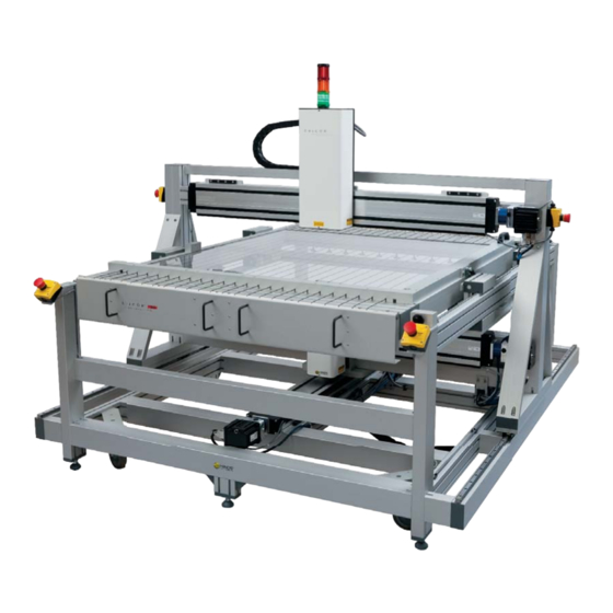
Exicor GEN5 Birefringence Measurement System Description Listed below are the main components of the Exicor GEN5 Birefringence Measurement System. Sample Scanning Module: Includes the components for generating the modulated beam of light and detecting the light as it exits the sample. -
Page 24: Figure 1.1 Scanning Module Main Components
Chapter 1: Overview of the Exicor GEN5 Birefringence Measurement System Figure 1.1 Scanning Module Main Components Exicor GEN5 User Manual... -
Page 25: Figure 1.2 Control System Main Components
Exicor GEN5 Birefringence Measurement System Description Control System: Controls and supplies power to all the hardware required for sample scanning and birefringence measurement. See Figure 1.2 for the component layout. The components of the Control System are: − Master Electrical Enclosure – Houses all power supplies and control electronics necessary for safe and efficient system operation. -
Page 26: General Dimensions
Chapter 1: Overview of the Exicor GEN5 Birefringence Measurement System General Dimensions Figure 1.3 General Dimensions Exicor GEN5 User Manual... -
Page 27: System Operating Requirements/Setup
Components within the system have been set for the customer’s native voltage prior to shipment. User adjustment should not be necessary. The Exicor GEN5 control system requires a single power outlet. The computer and monitor are powered from a power strip inside the control system. -
Page 28: Turning The Exicor Gen5 On And Off
Chapter 2: System Operating Requirements/Setup Turning the Exicor GEN5 On and Off The main power switch for the Exicor GEN5 is located on the front panel of the control system. Rotating the switch to the ON position will allow AC power from the wall to enter the Master Electrical Enclosure (MEE). -
Page 29: Operating The System
All operators should be aware of the Main Power Switch and Emergency OFF Switches for the Exicor GEN5 System. To ensure continued safety, all operators should familiarize themselves with the Operators' Safety Summary section, beginning on page 1. -
Page 30: Figure 3.1 Hardware Initialization Screen
If an error is witnessed during the initialization phase, identified by a red indicator, see section 7 “Troubleshooting” on page 75 for system initialization errors. Exicor GEN5 User Manual... -
Page 31: Status Lights
Status Lights Status Lights The Exicor GEN5 has 3 status lights mounted to the top of the Source Module as shown in the figure below. Figure 3.2 Status Light Location The meaning of each light is as follows: • GREEN: The system has initialized properly and is scanning or is ready to scan •... -
Page 32: Loading A Sample
Max View sample holder so that it 2 of its edges are touching both edges of the sample indexing corner as shown on the following page: Figure 3.3 Sample Placement on Exicor GEN5 Scanning a Sample The system can automatically scan various shapes using the automatic scan and macro functions. -
Page 33: Figure 3.4 Exicor Main Window At Startup
“Birefringence Plot” area of the software. Hold the mouse button and drag the pointer down to the lower right corner of the sample. See the following figure for an example of scanning a 1100 x 1300 mm sample. Exicor GEN5 User Manual... -
Page 34: Figure 3.5 Setting Up A 1100 X 1300 Mm Scan
ID, “DefaultID”. NOTICE The software uses the sample ID as the filename. If you do not choose a new name, any existing file with the name DefaultID.DAT is replaced with the new scan. Exicor GEN5 User Manual... -
Page 35: Figure 3.6 Confirm Scan Start Dialog Box
Scanning a Sample Figure 3.6 Confirm Scan Start Dialog Box 8. Click on the OK button in the Confirm Scan Start dialog box to begin the scan. Exicor GEN5 User Manual... -
Page 36: Scanning And Auto-Calibration Start
Angle, Magnitude & Angle, or Stress from the Graph Type list. When the scan is complete, X-Y Stage movement ceases and the birefringence plot area of the Exicor main window shows the complete results of your scan, as shown in Figure 3.8. Exicor GEN5 User Manual... -
Page 37: Figure 3.8 Completed Circular Scan
If you use the default sample ID, the new data replaces any data currently stored in the file “DefaultID.dat”. The steps you have just performed are sufficient for most applications. See chapter 4 Software Interface for other scan methods. Exicor GEN5 User Manual... -
Page 38: System Shutdown
Abort Scan button from the software interface. 2. Push the red power button on the front of the Control System. All systems outside the control system will shut down. 3. The PC and monitor can shut down independently as necessary. Exicor GEN5 User Manual... -
Page 39: Software Interface
Overview of the Graphical User Interface All measurement operations (scanning, saving data, generating statistics, etc.) are carried out from the computer screen. Figure 4.1, on the following page, shows the Exicor main window, after a rectangular scan has been completed. Exicor GEN5 User Manual... -
Page 40: Figure 4.1 Exicor Main Window Showing A Completed Rectangular Scan
Other buttons and panels in the window allow you to define the scan region, customize the scan, format the graph, etc. Each area and button of this window is further explained in this chapter. The main sections of the Exicor main window are shown in the following figure. Exicor GEN5 User Manual... -
Page 41: Menu Bar
The menu bar offers the following choices: File: controls related to new file creation, opening, saving, printing, copying data files, and exit. Recently opened files are shown and can be reopened by clicking on them. Exicor GEN5 User Manual... -
Page 42: File Identification
“Saving a File” on page 58 for more information on sample IDs. The File field displays the file name of the current data file. If you have not yet scanned or loaded a file, the File field is empty. Exicor GEN5 User Manual... -
Page 43: Interactive Scan
Overview of the Graphical User Interface The Macro field displays the macro currently loaded in memory. See Chapter 5 beginning on page 63 for information on using macros with the Exicor GEN5 system. Interactive Scan Figure 4.8 shows the Interactive Scan panel, located at the upper left-hand side of the Exicor GEN5 main window. -
Page 44: Automatic Scan
Figure 4.9 shows the Automatic Scan panel, located at the left-hand side of the Exicor main window under the Interactive Scan Panel. This panel is used to select scan region (Rectangular, Circular, Center-radius, or Stationary). See Making Birefringence Measurements on page 42. Figure 4.9 Automatic Scan Panel Exicor GEN5 User Manual... -
Page 45: Birefringence Plot Area
See the Troubleshooting chapter for more information. Figure 4.10 DC Level Indicator Figure 4.11 shows the Offsets, Notes, and Home & Reset buttons in the lower-left area of the Exicor window.. Exicor GEN5 User Manual... -
Page 46: Figure 4.11 Offsets, Home & Reset, Notes
The Statistics button shows the birefringence magnitude and fast axis angle statistics for the current scan. Figure 4.11 Offsets, Home & Reset, Notes Figure 4.12 shows the status bar located at the bottom of the Exicor GEN5 main window. Figure 4.12 Sample Thickness Indicator This bar shows the sample thickness that has been entered by the user. -
Page 47: Configuring The System
Stage Home Position Offset Configuration System Parameters Enable Auto Calibration Configuration Auto-Calibration Settings Auto-Calibration Location Configuration Auto-Calibration Settings Configuration System Parameters Num Offset Samples Configuration Auto-Calibration Settings Table 4.1 Summary of Where to Change System Parameters Exicor GEN5 User Manual... -
Page 48: System Parameters Control Window
This control sets the voltage range that is used by the lock-in amplifier for acquiring the detector signals. This has been set from the factory to the optimum setting for low birefringence LCD glass samples and should not need to be changed. Exicor GEN5 User Manual... - Page 49 Exicor software. This position is used as the 0,0 position for sample measurements. The stage offset fields are located under the Stage Settings section of the Settings tab. Click on the Get X Y button to set the home position to Exicor GEN5 User Manual...
-
Page 50: Auto-Calibration Settings Control Window
The Auto-Calibration feature is used to perform measurement offsets automatically before and during a sample scan. To access the Auto-Calibration settings, select Configuration-->Auto-Calibration Settings from the Exicor menu bar. Figure 4.14 Auto Calibration Settings Dialog Box Exicor GEN5 User Manual... - Page 51 Location box. The auto-calibration location must be a position in the X-Y- Note: Motion Stage where no sample is present and the beam is unobstructed (not passing through a sample). Once set, click OK to save settings. Exicor GEN5 User Manual...
-
Page 52: Making Birefringence Measurements
Area Measurements amounts of data with minimal user attention. Area measurement types available are rectangular and circular. Measurements are stored in a user-specified file. Exicor GEN5 User Manual... -
Page 53: Performing A Point Measurement
Using any of these techniques, the results of the measurement are displayed in the Retardation and Angle fields in the Interactive Scan panel. The fast axis angle measurement ranges from -90° to +90°. Use the following figure as a reference for fast axis angle measurements. Exicor GEN5 User Manual... -
Page 54: Figure 4.16 X-Y Motion & Fast Axis Angle
Figure 4.16 X-Y Motion & Fast Axis Angle If the Retardation field reads “BLOCKED”, this means there is not enough light getting to the detector. See Chapter 7 on page 75 for more information on dealing with “BLOCKED” measurement results. Exicor GEN5 User Manual... -
Page 55: Using Cursor Keys To Move The Stage Position
• Stationary: repeated measurement of a user-defined point in the scan area Set the shape of the scan region by clicking on the down-arrow next to the Scan Region field in the Automatic Scan panel. Exicor GEN5 User Manual... -
Page 56: Figure 4.17 Automatic Scan Panel For Rectangular Scans
Lower Right corner of the sample. Click on the Upper Left or Lower Right button in the Automatic Scan panel to set that scan coordinate to the current stage position. Exicor GEN5 User Manual... -
Page 57: Figure 4.18 Automatic Scan Panel For Circular Scans
A circular scan is defined by 3 points on the circumference of the circle. It is best to define the points to be far away from each other (as in the following figure). [0,0] Figure 4.19 Points to Define a Circular Scan Exicor GEN5 User Manual... -
Page 58: Figure 4.20 Defining A Circular Scan
Once the 3 points are defined, the Exicor software will trace out a circle showing the scan area. The following figure shows an example of a circular scan that has been defined. Figure 4.20 Defining a Circular Scan Exicor GEN5 User Manual... -
Page 59: Figure 4.21 Automatic Scan Panel For Center/Radius Scans
• Move the laser beam to the center of the sample and click the Center button. Move the laser beam to the edge of the sample and click the Radius button. Exicor GEN5 User Manual... -
Page 60: Figure 4.22 Defining A Center/Radius Scan
The stationary scan type is used to repeatedly measure the same X-Y point on a sample. To define a Stationary Scan, first, click on the down-arrow next to Scan Region in the Automatic Scan panel and select Stationary. Exicor GEN5 User Manual... -
Page 61: Figure 4.23 Automatic Scan Panel For Stationary Scans
Click on the Start Scan button. After the hardware is ready to scan, the Confirm Scan Start dialog box appears as shown in Figure 4.24. Enter the sample ID, or leave it blank for “DefaultID”, as described later in this chapter. Exicor GEN5 User Manual... -
Page 62: Figure 4.24 Confirm Scan Start Dialogue Box
File ---> Save. Enter the new sample ID when prompted if you want to change the sample ID. Then select the path and name of the file to which to save the data. Exicor GEN5 User Manual... -
Page 63: Viewing The Scan Results
• Mag & Angle: shows both the magnitude color plot with the angle vector plot overlaid on top. The fast axis angle cannot be shown while stress is the selected measurement type. • Mag 3D: shows a 3-dimensional surface representation of the retardation or stress magnitude. Exicor GEN5 User Manual... -
Page 64: Figure 4.26 Birefringence Plot Legend
2D plot. If this box is unchecked, the data points may become stretched in certain zoom conditions. Contour: checking this box displays contour lines overlaid on the color and vector plots. The contour lines enclose areas of different retardation magnitude. Exicor GEN5 User Manual... -
Page 65: Figure 4.27 Legend Settings Window
Scale” and “Spectral” color types display the color on a continuous gradient instead of in sub-ranges. Graph: Clicking on the “Graph Background” area or the “Scale Color” area allows the user to change the color of these areas of the Birefringence Plot area. Exicor GEN5 User Manual... -
Page 66: Figure 4.28 Statistics Dialog Box
The upper section of the window shows the statistics for the whole scan. If you have selected a region of the scan data with the mouse, the lower section displays statistics for only the selected data points. Click on Close to close the Statistics dialog box. Exicor GEN5 User Manual... -
Page 67: Managing Files
The sample ID associated with a file is shown in the Sample ID field in the Exicor main window. CAUTION Use these tips for sample IDs to avoid overwriting existing data files: • Enter a unique sample ID for each scan. • Avoid renaming files outside of the Exicor GEN5 software application. Exicor GEN5 User Manual... -
Page 68: Saving A File
• measurement data: the data points are listed in 2 separate grids. One grid contains the retardation magnitude data. The other grid contains the fast axis angle data. The data in each grid is sorted by X,Y position. Exicor GEN5 User Manual... -
Page 69: Creating A New File
• Filename and sample ID • Legend • Scan information: sensitivity, sample thickness, time and date, statistics, comments The image copied to the Windows Clipboard is similar to the output produced by printing your data (see the figure below). Exicor GEN5 User Manual... -
Page 70: Printing Files
2. Use your mouse to select the area you want to print. If you want to zoom in on certain data points, use the button or mouse wheel. 3. Select a graph type from the Graph to Display list. Exicor GEN5 User Manual... - Page 71 Print from the Exicor menu bar. This opens the Print dialog box. Use this as you would any other Windows Print dialog box. 5. Select the appropriate printing properties in the Print dialog box. 6. Click on the OK button. Exicor GEN5 User Manual...
- Page 72 Chapter 4: Software Interface Exicor GEN5 User Manual...
-
Page 73: Using Macros
You can accomplish this by using one of the shape tools or the Auto Detect Aperture button in the Edit Macro dialog box. The Auto Detect Aperture feature detects the outer edge of any aperture, but does not detect any blocked points within the aperture. Exicor GEN5 User Manual... -
Page 74: Creating A Macro
Save dialog box. Enter the filename of the saved macro, and click Save. The areas to be scanned by the macro appear as shaded regions on the 2D plot as shown in the figure below. Exicor GEN5 User Manual... -
Page 75: Loading A Macro
Select the macro file you want to load and click on the Load button. The loaded macro is listed in the Macro field at the top of the Exicor GEN5 main window. This macro is used for all subsequent scans until the macro is unloaded. -
Page 76: Editing A Macro
Load Macro from the Exicor menu bar.) Next, select Macro Edit Macro from the Exicor menu bar. The rest of the process is the same as for creating a macro, as discussed earlier in this chapter. Exicor GEN5 User Manual... -
Page 77: Maintenance And Cleaning
Maintenance and Cleaning The Exicor GEN5 requires very little maintenance. System Visual Check Check periodically and whenever the system is moved or maintained, that the covers on the Sample Scanning Module are secured properly. Be certain that no unwanted laser light escapes from the enclosure. -
Page 78: Consumables
2-3 years and the procedure should be done by a Hinds Instruments engineer or a factory trained representative. This schedule may vary according to the amount of time the system is powered on and the operating environment. -
Page 79: Fuses
Hinds Instruments Fan Filter Replacement The Exicor GEN5 has one cooling fan to control and stabilize the temperature of the system electronics. The inlet has a filter to keep dust and other particles out of the system. The filter is located at the front of the control system on the left side of the Master Electrical Enclosure (see the following figure). -
Page 80: Motion System Maintenance
Hinds PN 330-1000-017-R - Filter Replacement, 92mm SQ Fan Motion System Maintenance The Exicor GEN5 system actuators require periodic lubrication to ensure proper operation and the maximum actuator life time. This maintenance should be performed with the system power OFF to prevent harm to the operator. -
Page 81: X-Y Actuator Lubrication
The recommended lubrication interval is every 500 hours or 5,000 km, whichever comes first. Refer to the following figures for the lubrication points and the proper lubrication tool. Figure 6.4 Needle Point Adapter For Lubricating The X-Y Actuators Figure 6.5 Actuator Lubrication Port Locations Exicor GEN5 User Manual... -
Page 82: Guide Rail Bearing Lubrication
The recommended lubrication interval for the guide rail bearings is once per year. See the following figures for the lubrication ports of the guide rail bearings and the appropriate tool. Figure 6.7 Push-on Grease Fitting Adapter Exicor GEN5 User Manual... -
Page 83: Cleaning The Optics
If this occurs, clean the mirror with cotton swabs moistened with solvent. Wipe the surface gently while rotating the swab slowly. This action ensures that the contaminants are lifted away from the surface of the optic. See figure 6.4. Exicor GEN5 User Manual... -
Page 84: Cleaning The Exterior
Isopropyl alcohol and mineral solvent are examples of suitable materials. Acetone, MEK or Toluol are unsuitable. Cleaning the Exterior You can clean most exterior surfaces of the Exicor GEN5 with an ammonia-based cleanser (such as Windex). Do not allow any liquids to get inside the X-Y actuators CAUTION To avoid electrical shock and equipment damage, do not allow any liquids to get inside the Exicor GEN5. -
Page 85: Troubleshooting & Help
Troubleshooting & Help Diagnosing Common Errors Table 7.1 lists some errors you may encounter, and suggestions on how to interpret or fix the error. Exicor GEN5 User Manual... - Page 86 Communication cable to Electrical Enclosure motion controllers Error message: disconnected Use the cursor to move the other “problem direction. Actuators cannot travel Actuator at travel limit communicating with beyond preset factory limits the motion Restart software controllers” Exicor GEN5 User Manual...
- Page 87 Birefringence magnitude is large Offset correction not with no sample performed regularly present Perform air offset correction Offset correction not Birefringence performed after changing LIA magnitude is larger sensitivity than expected with sample present Exicor GEN5 User Manual...
-
Page 88: Other Error Messages
For example, check that the file is not in use by another program and ensure that there is enough free space on the disk to which the file is being written. Exicor GEN5 User Manual... -
Page 89: Contacting Hinds Instruments
Contacting Hinds Instruments Contacting Hinds Instruments If it is necessary to contact Hinds Instruments for support, refer to the following table for the company contact information. Method Information Monday - Friday 8:00 AM to 4:00 PM PST Telephone (503) 690-2000... - Page 90 Chapter 7: Troubleshooting & Help Exicor GEN5 User Manual...
-
Page 91: A Technical Specifications
Technical Specifications Power Requirements The Exicor GEN5 has been configured for the power connections of the customer’s factory and is designed to operate on the following: 115/230V ~, 9/4A, 50/60Hz General Description Exicor GEN5 is an integrated system for measuring low-level strain birefringence in thin, optically transparent samples up to 1100mm x 1300mm. -
Page 92: General
<1ºC during for one hour prior to and during measurement) Machine turned-on for minimum of 1 hour before test with auto-offset time interval of 5 minutes System tests performed in a laboratory environment (temperature 20 ± 1C) Exicor GEN5 User Manual... -
Page 93: Software Features
User Features • Copy file name from start scan dialogue • Abort button • Real-time measurement display updates • Data saved in .DAT or .DMT files using plain text tab-delimited format • Park button for sample loading Exicor GEN5 User Manual... - Page 94 Appendix A: Technical Specifications Exicor GEN5 User Manual...
-
Page 95: B Exicor Gen5 Limited Warranty
GEN5 Limited Warranty ® Hinds Instruments, Inc. warrants the Exicor GEN5 Birefringence measurement System to be free from defects in materials and/or workmanship for (1) year from the date of delivery, subject to the provisions contained herein. Hinds’ warranty shall extend to the original purchaser only and shall be limited to factory repair or replacement of defective parts. -
Page 96: Warranty Service
Repairs are warranted for ninety (90) days from the date of delivery. Reference section 7 (Troubleshooting & Help) on page 75 for contacting technical support. Exicor GEN5 User Manual... - Page 98 . h i n d s i n s t r u m e n t s . c o m COPYRIGHT © 2010 HINDS INSTRUMENTS, INC All Rights Reserved MANUFACTURED IN USA UNDER PATENTS & PATENTS PENDING...
Need help?
Do you have a question about the Exicor Gen5 and is the answer not in the manual?
Questions and answers