
Summary of Contents for BTM Tog-L-Loc
- Page 1 733679 User Guide: Bayonet Units Covers Standard Bayonet Style Hand Held Clinch Units. ® CORPORATION...
-
Page 2: Table Of Contents
Tooling Component Record (optional) Tog-l-loc/lance-n-loc User’s Guide section 7: Pneumatic Circuit section 8: Gun assembly Drawing booster assembly Drawing Disclaimer: BTM Reserves the right to ammend the contents of this manual without notice. Contact BTM to verify the latest revision. -
Page 3: Tog-L-Loc/Lance-N-Loc Overview
® ® system is the simple solution for fastening system which creates a strong mechanical plain or coated sheet metals. Tog-L-Loc forms joint without the use of external fasteners or ® a strong, leakproof joint without welding or welding. -
Page 4: Safety
2.0 safeTy UseR ResPonsIlbIlITy: Each person who is to operate or maintain the Tog-L-Loc unit must be familiar with these, and all other, safety precautions before attempting to use or to service the press equipment. The owner of the equipment is responsible to train and supervise all personnel as to safety precautions. -
Page 5: Start-Up Procedure
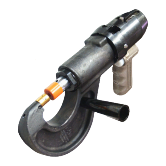
1. After removing your Tog-L-Loc/Lance-N-Loc system from its shipping box, make sure that you have received two sets of Tog-L-Loc, or Lance-N-Loc, tooling. One set is already installed in the gun. The second set should be in a package attached to the gun. Remove the second set of tooling and store it aside. - Page 6 Oil Level 6. Connect your air line to the booster. BTM recommends that the system operates at 80 PSI (5.5 Bar). Clean, dry air should be used. The removal of air supply is required before tool change or service.
- Page 7 Loosen plug with 5 mm Allen wrench. Note: If plug leaks oil after tightened, discontinue use and call BTM to order a replacement plug. 4. The bleeding procedure may need to be repeated several times to expel all of the air.
-
Page 8: Operation
3. Always hold the unit perpendicular to the work in both directions. THIS NOT THIS 4. Never attempt to make a Tog-L-Loc/Lance-N-Loc joint through another Tog-L-Loc/Lance-N-Loc joint, spot weld, or other obstruction. 5. The trigger must be pressed and held throughout the cycle to operate the unit. - Page 9 [90] [.040] Tog-L-Loc tools are preset by BTM to give best joining results with a specific range of metal type and thickness, as charted above. Higher strenths for a specific metal thickness may be obtained with optimized tooling from BTM. All Tog-L-Loc/Lance-N-Loc tools are marked with numbers for easy identification.
-
Page 10: Joint Adjustment Procedure
(If you reach 90 PSI, and you have not made a proper button dimension, per the Tooling Component Record, call BTM immediately, DO NOT go over 90 PSI.) Whenever tooling is changed, test the joints to see that they are still proper. If they are not, repeat... -
Page 11: Pneumatic Circuit
7.0 PneUMaTIC CIRCUIT all PneUMaTIC sInGle TRIGGeR ConTRol UnIT sPRInG-ReTURn boosTeR CylInDeR (bTM no. 711100e) boosTeR InseRT ValVe (bTM no. 017326) PneUMaTIC MUffleR (bTM no. 000695) aIR sUPPly 3-Way InseRT ValVe (PUsh bUTTon) (bTM no. 016121) Please note: The Push button is not considered part of the booster and is therefore not on the booster drawing. - Page 12 ® CORPORATION BTM has a wide range of products to meet your needs including (but definitely not limited to): PNEuMATIC CLAMPS & gRIPPERS ShEET METAL jOININg Light & heavy Duty Clamps Tog-L-Loc ® Clamps range from light duty BTM’s Tog-L-Loc sheet metal ®...
Need help?
Do you have a question about the Tog-L-Loc and is the answer not in the manual?
Questions and answers