Advertisement
Practical Instrument Electronics
1
EZ-Check™ Switch
Slide the switch to select from three user stored values
for the desired calibration points. The user can select HI,
DIAL, and LO positions. These values can easily be
changed to suit the calibration requirements.
Instructions for Enabling and Disabling the Configuration Options
1. Turn the Model 510/511 on with the ON/OFF Switch
2. Press the EZ-Dial Knob
CONFIGURATION" message is displayed.
3. Select options by turning the EZ-Dial Knob until the arrow points
to the desired option.
4. The option can be enabled or disabled by tapping the EZ-Dial
Knob.
The Model 510/511 configuration menu will exit automatically after 5
seconds of inactivity and go to normal operation with the options selected.
These options are recalled at turn on until they are changed again.
841 Holt Road #1 • Webster, NY 14580
Practical Instrument Electronics, Inc. Copyright 2003. All rights reserved.
Basic Keypad Operations
3
while the "PRESS EZ-DIAL KNOB FOR
Tel: 585-872-9350 • Fax: 585-872-2638
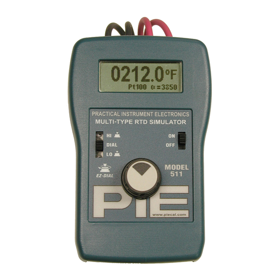
Model 510/511
RTD Simulator(s)
Operating Instructions
2
ON/OFF Switch
Slide the ON/OFF to turn the Model 510/511
on or off.
3
EZ-Dial™ Knob
The EZ-Dial™ Knob has two adjustment
speeds. Simply turning the EZ-Dial™ Knob will
select fine adjustments. While pressing down
and turning the EZ-Dial™ Knob will make
course adjustments.
Note: When the EZ-Check™ Switch is in the
HI or LO position, pressing and holding the EZ-
Dial™ Knob without turning will store a new
HI or LO EZ-Check
2
.
sales@piecal.com • http://www.piecal.com/
510/511-9002 2/25/04
value.
1-4
Advertisement
Table of Contents

Related Manuals for PIE 510

Summary of Contents for PIE 510
- Page 1 value. Model 510/511 Configuration Instructions for Enabling and Disabling the Configuration Options 1. Turn the Model 510/511 on with the ON/OFF Switch 2. Press the EZ-Dial Knob while the “PRESS EZ-DIAL KNOB FOR CONFIGURATION” message is displayed. 3. Select options by turning the EZ-Dial Knob until the arrow points to the desired option.
- Page 2 This ctile feature allows continuous monitoring of the device being calibrated without looking back at the odel 510/511 display. This is also useful in poor lighting or under difficult operating conditions. 841 Holt Road #1 • Webster, NY 14580 Tel: 585-872-9350 •...
- Page 3 Model 510/511 Operating Instructions Connection Diagrams Two Wire Connection to Transmitter Three Wire Connection to Transmitter Four Wire Connection to Transmitter 841 Holt Road #1 • Webster, NY 14580 Tel: 585-872-9350 • Fax: 585-872-2638 sales@piecal.com • http://www.piecal.com/ Practical Instrument Electronics, Inc. Copyright 2003. All rights reserved.
- Page 4 The equipment will be repaired, replaced or adjusted at our option. The liability of Practical Instrument Electronics (PIE) is restricted to that given under our guarantee. No responsibility is accepted for damage, loss or other expense incurred through sale or use of our equipmen t.
Need help?
Do you have a question about the 510 and is the answer not in the manual?
Questions and answers