Table of Contents
Advertisement
Quick Links
Advertisement
Table of Contents

Summary of Contents for Eurofred daitsu ACCD WC4 Series
- Page 1 USER MANUAL WIRED CONTROLLER ACCD_WC4 Serie Edition ACCD_WC4 Models ACCD_WC4...
- Page 2 To Users Thank you for selecting Daitsu´s product. Please read this instruction manual carefully before installing and using the product, so as to master and correctly use the product. In order to guide you to correctly install and use our product and achieve expected operating effect, we hereby instruct as below: (1) This appliance is not intended for use by persons (including children) with reduced physical, sensory or mental capabilities, or lack of experience and...
-
Page 3: Table Of Contents
Contents 1 Safety Notices (Please be sure to abide) ..........1 2 Display....................2 2.1 Appearance .................. 2 2.2 Instructions for Related Displayed Symbols ......... 3 3 Buttons ..................... 6 3.1 Button Graphics................6 3.2 Function Instructions of Buttons ............7 4 Operation Instructions ................ - Page 4 4.7.8 Auxiliary Heating Function Setting ..........20 4.7.9 Dry Function Setting.............. 20 4.7.10 Filter Clean Reminder Setting ..........20 4.7.11 Quiet Function Setting ............21 4.7.12 Fahrenheit Temperature Setting ..........21 4.7.13 Fixed-angle Swing Mode Setting ..........21 4.7.14 Low-temperature Drying Function Setting......... 21 4.7.15 WiFi Function Setting ............
- Page 5 5 Installation Instructions ............... 40 5.1 Parts and Dimension of Wired Controller........... 40 5.2 Installation Requirements .............. 41 5.3 Installation Methods..............42 5.4 Disassembly ................43...
-
Page 6: Safety Notices (Please Be Sure To Abide)
1 Safety Notices (Please be sure to abide) Warning: If not abide strictly, it may cause severe damage to the unit or the people. Note: If not abide strictly, it may cause slight or medium damage to the unit or the people. This sign indicates that the operation must be prohibited. -
Page 7: Display
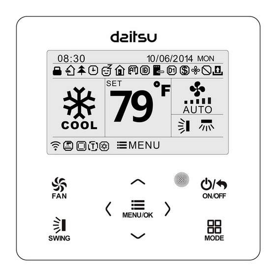
2 Display Appearance Figure 2-1 Appearance of wired controller... -
Page 8: Instructions For Related Displayed Symbols
Instructions for Related Displayed Symbols Table 2.2.1 Instructions for Related Displayed Symbols Symbols Instructions Up and down swing function Left and right swing function Fresh air function Sleep function Auto mode Cooling mode Dry mode Fan mode Heating mode Health function I-Demand function Holiday function Shielding status (Buttons, temperature, ON/OFF, mode... - Page 9 Symbols Instructions Current set fan speed Memory function (Memory in power failure) Save function Dry function Remind to clean the filter Timer on status Gate card pulled-off status or nobody presented status Quiet function Function lock WiFi is turned on Independent swing is turned on Setback function is turned on...
- Page 10 Symbols Instructions Auxiliary heating status Display of set temperature: the temperature shown in the diagrams of this manual is in Fahrenheit scale(℉). Temperature display in Fahrenheit scale and Celsius scale can be selected. Please refer to the setting by the user.
-
Page 11: Buttons
3 Buttons Button Graphics Figure 3-1 Button graphics... -
Page 12: Function Instructions Of Buttons
Function Instructions of Buttons Table 3.2.1 Function Instructions of Buttons Button name Button Function Set low speed, low-medium speed, medium speed, medium-high speed, high speed, turbo and auto speed. ∧ (1)Set temperature (2)Set parameter ∨ (3)Move option cursor (1)Turn on or turn off unit ON/OFF (2)Return to previous page Set up&down swing and set left&right... - Page 13 other functions can be set in corresponding submenu. Detailed menu structure is as shown in the Fig. as below. Figure 4-1 Menu structure...
-
Page 14: On/Off
On/Off When the wired control is on main page, press “ON/OFF” button to turn on the unit. Press “ON/OFF” button again to turn off the unit. The interfaces of On/Off status are shown in the Fig. as below. Figure 4-2 Unit off page... -
Page 15: Mode Setting
Figure 4-3 Unit on page Mode Setting Under on status, press “MODE” button on the main page can set mode circularly as below. Figure 4-4 Mode Setting Note: (1) If save function is turned on, auto mode is not available. (2) Heating mode is not avaiable for the cooling only unit. -
Page 16: Temperature Setting
Temperature Setting Under on status, press “∧” or “∨” button on the main page to increase or decrease set temperature by 1℃(1℉); hold “∧” or “∨” button to increase or decrease set temperature by 1℃(1℉) every 0.3s. In cooling, dry, fan and heating mode, temperature setting range is 16℃~30℃ (61℉~86℉). -
Page 17: Functions Setting
Select up&down swing and left&right swing through “<” or “>” button. When left&right swing is selected. Left&right swing angle will be adjusted circularly as below: Figure 4-7 left&right swing Note: (1) Turn on fixed-angle swing mode in function setting page. (2) If fixed-angle swing is not available for the model, fixed-angle swing will be invalid when the wired controller turns on fixed-angle swing mode. - Page 19 Figure 4-8 Function setting Function introduction is shown in the table as below. Table 4.7.1 Function introduction Function Instruction Adjust indoor fresh air volume to improve air quality and Fresh air keep indoor air fresh. (The unit needs to be installed with a function new damper).
- Page 20 Function Instruction I-Demand Unit will operate under save mode to save energy. function In the heating mode, when the user goes out, it is used to Holiday function maintain the indoor ambient temperature to ensure turbo heating when the user comes back. When the power is restored after power failure, the indoor Memory function unit resumes the original status.
-
Page 21: Fresh Air Function Setting
Function Instruction Fixed-angle Switch between simple swing and fixed-angle swing to swing mode satisfy user’s requirement. Low-temperature The unit runs the dry mode at a lower set temperature to drying function improve the drying capacity. After shutdown, the unit will automatically run to ensure that the indoor ambient temperature is within the set temperature Setback function range. - Page 22 Table 4.7.2 Mode Instruction Mode Instruction The unit continuously runs for 60min, and fresh air valve runs for 6 min. The unit continuously runs for 60min, and fresh air valve runs for 12 min. The unit continuously runs for 60min, and fresh air valve runs for 18 min.
-
Page 23: Sleep Function Setting
4.7.2 Sleep Function Setting Under on status, after entering into user function page, press “∧” or “∨” button to select sleep function and press “<” or “>” button to turn on or turn off sleep function with auto saving. Note: (1) Under fan or auto mode, sleep function is not available. -
Page 24: Memory Function Setting
select holiday function option and press “<” or “>” button to turn on or turn off this function with auto saving. Note: (1) This function is only available in heating mode. (2) When this function has been set, set temperature is displayed in 8℃(46℉). In this case, temperature setting and fan speed setting are shielded. -
Page 25: Auxiliary Heating Function Setting
4.7.8 Auxiliary Heating Function Setting Under on status, after entering into user function page, press “∧” or “∨” button to select auxiliary heating function and press “<” or “>” button to turn on or turn off this function with auto saving. Note:... -
Page 26: Quiet Function Setting
Whenever you turn off this function, the unit’s operating time will be zero clearing. 4.7.11 Quiet Function Setting Under on status, after entering into user function page, press “∧” or “∨” button to select quiet function and press “<” or “>” button to turn on or turn off this function with auto saving. -
Page 27: Wifi Function Setting
select low-temperature drying function and press “<” or “>” button to turn on or turn off this function with auto saving. Note: (1) This function is only available in dry mode. (2) When low-temperature drying function is turned on, the displayed set temperature in dry mode is 12℃(54℉). -
Page 28: Panel Lifting Function Setting
(1)Once it have entered into independent swing setting page, press “∧” or “∨” button to select the air outlet (there are four air outlet on the panel marked by the circles. The number is 1, 2, 3 and 4. The number of “0” of air outlet is corresponding to the number of circles of air outlet on the panel) and then press “<”... -
Page 29: Language Setting
function setting page. Press “∧” or “∨” button to control the up, down or stop for the panel. Press “ON/OFF”button to reset the panel. The reset window is displayed, which indicates the reset is processing. Once the panel reset is finished, it will resume to the main page automatically. - Page 30 Figure 4-10 Status View...
-
Page 31: Current Error View
The following statuses can be viewed: if defrosting is operating; if auxiliary heating is operating; residual time of filter cleaning reminder; indoor ambient temperature; outdoor ambient temperature. Note: (1) The residual time of filter cleaning reminder is valid only when the cleaning reminder function is turned on. - Page 32 Figure 4-11 Current Error View...
-
Page 33: Timer Setting
4.10 Timer Setting The wired controller can set 6 kinds of timer: one time clock timer, everyday timer, one week timer, two week timer, countdown timer on and countdown timer off. Select timer symbol after entering menu page. Press“MENU/OK” button to enter timer setting page. -
Page 34: Daily Timer
button to turn on or turn off it. Press “MENU/OK” button to enter timer time setting page. Please refer to the Fig. as below. Figure 4-13 one time clock timer Press “<” or “>” button to select timer hour or minute and press “∧” or “∨” button to adjust time. -
Page 35: Weekly Timer
cooling), set temperature in heating (it is valid only when the current mode is heating). Please refer to the Fig. as below. Figure 4-14 Daily timer setting After entering daily timer setting page, press “<” or “>” button to select setting item. -
Page 38: Two Week Timer
Figure 4-15 Weekly timer setting 4.10.4 Two Week Timer The user can set the everyday timer content for two weeks. In each day, the user can set eight segments of timer content. The unit will execute corresponding timer setting in two weeks. In the timer setting page, press “∧”... -
Page 39: Countdown Timer
or “∨” button to select current week and then press “<” or “>” button to set current week as first week or second week. Please refer to the Fig. as below. Figure 4-16 Setting of current week After entering two week timer menu page, press “∧” or “∨” button to select the two week schedule and then press “MENU/OK”... - Page 40 on can be set simultaneously. If timer off in “x” hours and timer on in “y” hours are set simultaneously in unit on status, the unit will be off in “x” hours and then the unit will be on in “y” hours after timer off. After entering into timer on setting page, press “∧”...
-
Page 41: Clock Setting
decreases time by 0.5h. Press“ON/OFF” button to return to the previous page. Please refer to the Fig. as below. Figure 4-18 Countdown timer off If timer function is turned on, the set hours will decrease as the unit operation time increases. In this case, residual hours can be viewed after entering timer setting page. -
Page 42: Clock Setting
“>” button to select 12-hour system or 24-hour system. Please refer to the Fig. as below. Figure 4-19 Time format selection 4.11.2 Clock Setting Select clock symbol in menu page and then press “MENU/OK” button to enter clock setting page. Press “∧” or “∨” button to select time set and then press “MENU/OK”... - Page 43 Figure 4-20 Clock setting...
-
Page 44: Lock Setting
4.12 Lock Setting Select lock symbol in menu page and then press “MENU/OK” button to enter into the lock setting page. Press “∧” or “∨” button to select the item to be locked and then press “<” or “>” button to lock or unlock. Please refer to the Fig. as below. -
Page 45: Installation Instructions
5 Installation Instructions Parts and Dimension of Wired Controller Figure 5-1 Dimension of wired controller Figure 5-2 Parts of wired controller... -
Page 46: Installation Requirements
Table 5.1.1 Standard parts Tapping Panel of Soleplate of screw Name wired Screw M4×25 wired ST3.9X25 controller controller Quantity Installation Requirements (1) Prohibit installing the wired controller at wet places. (2) Prohibit installing the wired controller at the places with direct sunshine. (3) Prohibit installing the wired controller at the place near high temperature objects or water-splashing places. -
Page 47: Installation Methods
Installation Methods Figure 5-3 Installation diagram for wired controller The above Fig. is the simple installation process of wired controller; please pay attention to the following items: (1) Before installation, please cut off the power for indoor unit. -
Page 48: Disassembly
(2) Pull out the 2-core twisted pair wire from the installation hole on wall, and pull this wire through the “∩” hole at the rear side of the soleplate of wired controller (3) Stick the soleplate of wired controller on the wall and then use tapping screw ST3.9X25 MA or screw M4×25 to fix soleplate and installation hole on wall together. - Page 49 Eurofred S.A. Marqués de Sentmenat 97 08029 Barcelona www.eurofred.es...
Need help?
Do you have a question about the daitsu ACCD WC4 Series and is the answer not in the manual?
Questions and answers
What app do I need to enable and use the AC through WiFi?