Advertisement
Quick Links
Advertisement

Summary of Contents for APS Gold-Wave GW-10
- Page 1 ._____________ Serial no The Finest in Equipment for the Electronics Industry...
-
Page 2: System Inventory
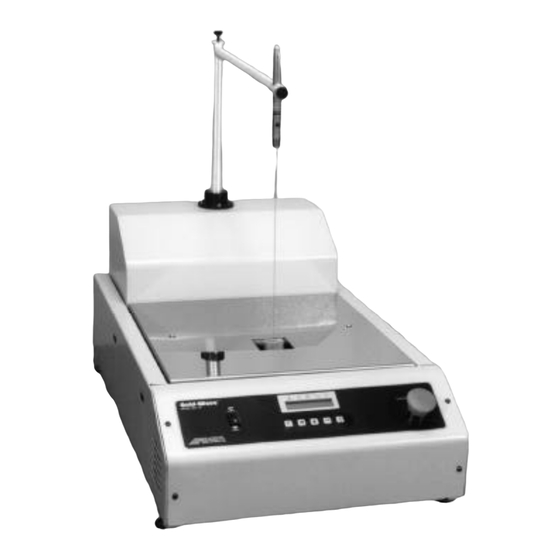
I. SYSTEM INVENTORY A. Base Unit B. One (1) foot pedal C. Laser pointer assembly D. Power cord E. Blow-through nozzle assembly (Model GW-10A only) F. Solder nozzle NOTE: Any section refering to blow-through (blowoff) nozzle pertains only to systems with that option included. - Page 3 Rear view of base unit Fig. 1 V. INSTALLATION & SET-UP (Refer to Figs. 1, 2 & 3) A. Placement of the unit: The GW-10 needs a stable benchtop for set-up. I m p o r t a n t, Using a horizontal b u bble level, adjust the four leveling feet until the machine is properly leveled.
- Page 4 5. When solder falls below recommended level, add solder until the proper level is reached. 6. Replace top insulation, and board holder plate. 7. Turn machine ON at rear of unit: When machine is first turned on, display will show RUN mode and program (00) will show factory set parameters. Heating elements will begin melting solder to set temperature.
- Page 5 INSTALLING OR CHANGING THE NOZZLE: CAUTION: SOLDER IS HOT! CAUTION: USE SAFETY PRECAUTIONS WHEN PERFORMING THIS OPERATION. USE SAFETY GLASSES, FACE SHIELD, HIGH TEMPERATURE GLOVES, & APRON. CAUTION : Nozzle must be completely dry of any moisture (from cleaning etc.) prior to immersing in solder bath.
- Page 6 Laser Light Locator Laser Locator Assembly Insulation Board Holder Plate Pump Motor Solder Housing Nozzle Board Holder Cooling Fan Height Adjustment Knobs Control Panel Pump Motor Solder Pressure Chamber Bottom Impeller Leveling Feet Bayonet-mount Foot pedal nozzle connection Fig. 3...
- Page 7 Air nozzle Insert position switch position Emergency stop (option) 65 ON RUN Same as E-stop -press any key to reset Remove position Enter key Fig. 4 Increment key Cursor key Function key Wave height (%) Wave time (sec.) Blow-off time Program # Set point temp °C...
- Page 8 B. Front Panel: The keys: There are five keys on the controller. [ F ] Function key changes the status of the machine. By pressing this key you can toggle the machine to RUN mode or EDIT mode. In EDIT mode parameters can be changed as required. In RUN mode, the machine is ready for use per the pre-set parameters.
- Page 9 E. Changing Programs: To change to a different program, press [ F ], Prg/EDIT will be displayed, press [ to change the program #, then press [ F ] to switch the machine into the RUN mode. F. Editing Parameters: 1.
-
Page 10: Maintenance
VII. REMOVING AND REPLACING THROUGH-HOLE COMPONENTS (ENSURE THAT YOU ARE IN AUTO MODE) A. Prepare board surface and component to be inserted appropriately B. Ensure laser light locator is centered in wave nozzle C. Enter program # desired (in edit mode) Insert D. - Page 11 XI. TROUBLESHOOTING SOLDERABILITY If all variables and parameters which lead to good solderability are not properly controlled, some typical defects will occur. The description and causes of some common defects are listed below. 1. Poor Wetting: Wetting is the primary factor in achieving good solder joints. A condition when the surfaces to be joined are only partially covered with molten solder, leaving areas of unwetted surfaces, behind is called non-wetting or poor wetting.
-
Page 12: Troubleshooting Machine
Bridging occurs when excess solder shorts two adjacent pads, conductors or leads. XII. TROUBLESHOOTING MACHINE Failure Corrective Measures Solder does not melt Check the circuit breaker, solid state relays and heaters. If the circuit breaker is tripped, turn it on. If the SSR is fused, replace it. - Page 13 To thermocouple Solder pump SSR for Transformer control heaters Terminal block Emergency stop Controller board Position switch Fig. 6 (See electrical schematics for details) -11-...
- Page 14 Mounting Screws (4) GW-UBF 1. Mount UBF using 4 mounting screws 2. Slide 2 sheet metal covers in from front of machine on either side of nozzle 3. Adjust paths using thumb screws to position PC board between fingers 4. Operate machine using GW-10 operating manual...
- Page 15 For GW-10/10A with Nitrogen Option Adjusting Nitrogen Flow 1. Supply nitrogen at 60 psi (4 bars) 2. Machine must be heated up to soldering temperature 3. Close N 2 standby valve completely by inserting flat screwdriver and turning clockwise 4. Open flow meter valve fully by turning flow meter knob counterclockwise 5 .
-
Page 16: Spare Parts List
GW-10 SPARE PARTS LIST BASE UNIT GW-10-MB main control board GW-10-CO controller overlay GW-10-PM pump motor GW-10-PB pump bearing GW-10-HP high pressure pump assembly GW-10-MP motor pulley GW-10-FAN cooling fan GW-10-CORD AC cord GW-10-BLT belt GW-10-SPT solder pot GW-10-HTR heating element GW-10-HW heater wire assembly complete GW-10-PI...
Need help?
Do you have a question about the Gold-Wave GW-10 and is the answer not in the manual?
Questions and answers