Advertisement
Quick Links
ANALOG TO RELAY
INTERFACE SERIES
Installation & Operation Instructions
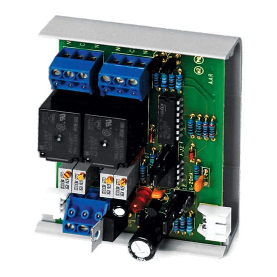
AAR
GENERAL INFORMATION
The AAR is controlled by a single analog input signal
with two potentiometers controlling each output
relay. The two 10 amp output relays can be
independently set to xed or adjustable deadband.
"Fixed", the relay will turn "ON" at the level set by the
Low pot and will turn "OFF" at a xed 3% of the input
signal below the turn-on level. "Adjustable" allows a
exible range of deadband adjustment using both
the
High
and
Low
edge-connector feature allows signal and power
connections to be extended to the next board. This
allows the installer to wire the rst unit, then slide
additional units together by plugging into a power,
and signal bus without the need to strip and
terminate additional wires. The AAR is
calibratable, however, factory calibration is available
upon request for an additional charge. Relay trip
points can be factory calibrated, saving installation
time and expense.
MOUNTING INSTRUCTIONS
The interface device can be mounted in any position. If circuit board slides out of snap track, a
non-conductive "stop" may be required. Use only ngers to remove board from snap track. Slide out of
snap track or push up against side of snap track and lift that side of the circuit board to remove. Do not
ex board or use tools.
WIRING INSTRUCTIONS
PRECAUTIONS
• Remove power before wiring. Never connect or disconnect wiring with power applied.
•
When using a shielded cable, ground the shield only at the controller end. Grounding both
ends can cause a ground loop.
• It is recommended you use an isolated UL-listed class 2 transformer when powering the unit
with 24 VAC. Failure to wire the devices with the correct polarity when sharing transformers may
result in damage to any device powered by the shared transformer.
• If the 24 VDC or 24VAC power is shared with devices that have coils such as relays, solenoids, or
other inductors, each coil must have an MOV, DC/AC Transorb, Transient Voltage Suppressor (ACI
Part: 142583), or diode placed across the coil or inductor. The cathode, or banded side of the DC
Transorb or diode, connects to the positive side of the power supply. Without these snubbers,
coils produce very large voltage spikes when de-energizing that can cause malfunction or
destruction of electronic circuits.
• All wiring must comply with all local and National Electric Codes.
Automation Components, Inc.
2305 Pleasant View Road | Middleton, WI 53562
Phone: 1-888-967-5224 | Website: workaci.com
potentiometer.
The
eld
Page 1
FIGURE 1: DIMENSIONS
BOARD
3.25" (82.55mm)
2.42"
(61.46mm)
SNAP TRACK
3.25" (82.55mm)
2.70"
(68.58mm)
Phone: 1-888-967-5224
Website: workaci.com
0.70" (17.78mm)
Version: 1.0
I0000467
Advertisement

Related Manuals for aci AAR

Summary of Contents for aci AAR
- Page 1 • If the 24 VDC or 24VAC power is shared with devices that have coils such as relays, solenoids, or other inductors, each coil must have an MOV, DC/AC Transorb, Transient Voltage Suppressor (ACI Part: 142583), or diode placed across the coil or inductor. The cathode, or banded side of the DC Transorb or diode, connects to the positive side of the power supply.
- Page 2 FIGURE 2: WIRING Set Jumper Switch for Signal Input Ranges 0-20mA 0-20mA 0-12V 0-20mA 0-24V 0-20mA A 1 F Relay 1 Analog Relay 2 24 VAC/DC Input Power Supply Signal Calibration Each relay can be individually set for a Fixed or Adjustable deadband. Place jumper shunts for relay 1 or 2 on A for adjustable or F for xed (or a combination of each).
- Page 3 APPLICATION NOTES Two unique uses for the AAR that may solve a problem for you. Problem: From one analog signal I want to turn ON a load when the analog signal increases to a certain value, and if it continues to increase, OFF again.
- Page 4 Snaptrack Flammability Rating: UL94 V-0 WARRANTY The ACI AAR Series is covered by ACI’s Two (2) Year Limited Warranty, which is located in the front of ACI’S SENSORS & TRANSMITTERS CATALOG or can be found on ACI’s website: www.workaci.com. W.E.E.E. DIRECTIVE At the end of their useful life the packaging and product should be disposed of via a suitable recycling centre.
Need help?
Do you have a question about the AAR and is the answer not in the manual?
Questions and answers