
Related Manuals for Racal Instruments 3152B

Summary of Contents for Racal Instruments 3152B
- Page 1 sales@artisantg.com artisantg.com (217) 352-9330 | Click HERE Find the Astronics / EADS / Racal 3151 at our website:...
- Page 2 Racal Instruments™ 3152B VXIbus Arbitrary Waveform Generator User Manual Also including the 3151B, 3100M, and 3100R Publication No. 980935 Rev. A EADS North America Test and Services a division of EADS North America, Inc. 4 Goodyear, Irvine, CA 92618 Tel: (800) 722-2528, (949) 859-8999; Fax: (949) 859-7139 info@eads-nadefense.com...
- Page 3 THANK YOU FOR PURCHASING THIS EADS NORTH AMERICA TEST AND SERVICES PRODUCT For this product, or any other EADS North America Test and Services a division of EADS North America, Inc. (“EADS North America Test and Services”) product that incorporates software drivers, you may access our web site to verify and/or download the latest driver versions.
- Page 4 RETURN of PRODUCT Authorization is required from EADS North America Test and Services before you send us your product for service or calibration. Call or contact the Customer Support Department at 1-800-722-3262 or 1-949-859- 8999 or via fax at 1-949-859-7139. We can be reached at: helpdesk@eads-nadefense.com. PROPRIETARY NOTICE This document and the technical data herein disclosed, are proprietary to EADS North America Test and Services, and shall not, without express written permission of EADS North America Test and Services, be...
- Page 5 FOR YOUR SAFETY Before undertaking any troubleshooting, maintenance or exploratory procedure, read carefully the WARNINGS and CAUTION notices. This equipment contains voltage hazardous to human life and safety, and is capable of inflicting personal injury. If this instrument is to be powered from the AC line (mains) through an autotransformer, ensure the common connector is connected to the neutral (earth pole) of the power supply.
- Page 6 Artisan Technology Group - Quality Instrumentation ... Guaranteed | (888) 88-SOURCE | www.artisantg.com...
- Page 7 This page was intentionally left blank. Artisan Technology Group - Quality Instrumentation ... Guaranteed | (888) 88-SOURCE | www.artisantg.com...
-
Page 8: Table Of Contents
What’s in This Manual ......................... 1-1 What’s in This Chapter ........................ 1-2 Conventions Used in this Manual ....................1-2 Introduction..........................1-2 3152B Feature Highlights ......................1-3 ArbConnection Feature Highlights ....................1-4 General Description........................1-6 Output Waveforms........................1-6 Run Modes ..........................1-7 Frequency Control and Accuracy .................... - Page 9 Continuous Mode ........................1-20 Triggered Mode ........................1-20 Gated Mode ..........................1-20 Burst Mode ..........................1-20 Trigger Sources..........................1-20 Modulation Run Modes ......................1-21 Synchronization of Multiple 3152B Modules ................1-21 PLL Synchronization ........................1-21 Phase Modulation ........................1-22 Filters............................1-22 Output State ..........................1-22 Programming the 3152B ......................1-23 Chapter 2 Installation ....................2-1 Preparation for Use ........................2-1...
- Page 10 Publication No. 980935 Rev. A 3152B User Manual Re-Triggered Run Mode ......................3-8 Gated Run Mode ........................3-8 Burst Run Mode........................3-9 Selecting the Trigger Source..................... 3-10 Selecting the Trigger Level......................3-11 Selecting the Trigger Slope ....................... 3-11 Using Trigger Delay........................3-12 Activating the Backplane TTLTrg Lines..................
- Page 11 3152B User Manual Publication No. 980935 Rev. A Main Window..........................4-3 Control Panels..........................4-3 The Operation Panels.......................4-5 Output ...........................4-6 Run Mode..........................4-8 Standard ..........................4-9 Arbitrary/Sequence ......................4-11 Using the Memory Partition Table..................4-13 Using Waveform Studio ......................4-15 Half Cycle..........................4-19 The Modulation Panels ......................4-19 FM ............................4-20 AM............................4-22...
- Page 12 Invoking HS Command Mode ....................5-5 Rules for Using HS Command Mode..................5-6 Legacy vs. Modern Command Set ..................5-7 3152B Legacy Commands ......................5-8 EADS North America Test and Services Artisan Technology Group - Quality Instrumentation ... Guaranteed | (888) 88-SOURCE | www.artisantg.com...
- Page 13 3152B User Manual Publication No. 980935 Rev. A 3100R/M-3152B Commands......................5-13 Instrument & Output Control Commands ...................5-23 Run Mode Commands .......................5-37 Standard Waveform Control Commands ...................5-43 Arbitrary Waveforms Control Commands...................5-50 The Apply Control Commands ....................5-58 Using the Apply Commands.......................5-58 Sequenced Waveforms Control Commands ................5-65 Modulated Waveform Global Control Commands ..............5-71...
- Page 14 Publication No. 980935 Rev. A 3152B User Manual Frequency Accuracy ........................ 6-3 Frequency Accuracy, Internal Reference................6-3 Frequency Accuracy, External 10MHz Reference ............... 6-4 Amplitude Accuracy ......................... 6-4 Amplitude Accuracy, DAC Output ..................6-4 Amplitude Accuracy, DDS Output ..................6-5 Offset Accuracy ........................
- Page 15 3152B User Manual Publication No. 980935 Rev. A Gated FM - Standard Waveforms ..................6-27 Re-triggered FM Bursts - Standard Waveforms..............6-28 FM - Arbitrary Waveforms ....................6-29 AM............................6-29 FSK .............................6-30 PSK .............................6-31 ASK .............................6-31 Variable Dwell Time Frequency Hopping................6-32 Fix Dwell Time Frequency Hopping ..................6-33 Amplitude Hopping......................6-33...
- Page 16 Publication No. 980935 Rev. A 3152B User Manual Setup 16 ..........................7-12 Setup 17 ..........................7-13 Offset Adjustments ........................7-13 Setup 18 ..........................7-13 Setup 19 ..........................7-13 Setup 20 ..........................7-14 Setup 21 ..........................7-14 Setup 22 ..........................7-14 Setup 23 ..........................
- Page 17 Updating Message-Based Firmware ..................7-32 Chapter 8 Product Support...................8-1 Product Support ...........................8-1 Warranty............................8-1 Return of Product .........................8-1 Reshipment Instructions.......................8-1 Appendix A 3152B Specifications ................A-1 Outputs............................A-1 Main Output.......................... A-1 Square Wave, Pulse Performance..................A-1 Sync Output ......................... A-1 Filters............................A-1 General Run Modes ........................
- Page 18 Publication No. 980935 Rev. A 3152B User Manual Amplitude Hopping....................... A-7 FSK ............................A-7 PSK ............................A-7 ASK ............................A-8 3D............................A-8 Pulse Generator Waveform Characteristics ................A-8 Half-Cycle Waveform Generator Characteristics................. A-9 Counter/Timer Characteristics..................... A-9 Frequency, Period Averaged ....................A-9 Period, Pulse Width......................
- Page 19 3152B User Manual Publication No. 980935 Rev. A This page was intentionally left blank. EADS North America Test and Services Artisan Technology Group - Quality Instrumentation ... Guaranteed | (888) 88-SOURCE | www.artisantg.com...
- Page 20 Figure 1-4, ArbConnection Pulse Composer Example ..............1-5 Figure 1-5, ArbConnection Serial Data Composer Example ............1-6 Figure 1-6, Configurations: 3151B, 3152B, 3100R-3152B, and 3100M-3152B......1-11 Figure 1-7, Segment 1 – Sine (x)/x Waveform................1-16 Figure 1-8, Segment 2 – Sine Waveform..................1-16 Figure 1-9, Segment 3 –...
- Page 21 Figure 4-65, Command Editor......................4-83 Figure 4-66, Log File Example.......................4-84 Figure 5-1, Definite Length Arbitrary Block Data Format ...............5-53 Figure 5-2, 3152B 16-bit Waveform Data Point Representation............5-54 Figure 5-3, 3152A 12-bit Waveform Data Point Representation............5-54 Figure 5-4, Segment Address and Size Example ................5-57 Figure 5-5, 64-bit Sequence Table Download Format ..............5-67...
- Page 22 List of Tables Table 2-1, Valid and Invalid IP Addresses for Subnet Mask 255.255.255.0........2-5 Table 5-1, 3152B SCPI Command Summary for 3152A Emulation..........5-8 Table 5-2, 3152B SCPI Command Summary ................5-14 Table 5-3, Instrument & Output Control Commands Summary ............ 5-23 Table 5-4, Run Mode Commands ....................
- Page 23 3152B User Manual Publication No. 980935 Rev. A Table 6-30, Pulse Width Measurement Accuracy................6-37 Table 7-1, Recommended Calibration for Adjustments ..............7-2 EADS North America Test and Services Artisan Technology Group - Quality Instrumentation ... Guaranteed | (888) 88-SOURCE | www.artisantg.com...
- Page 24 Publication No. 980935 Rev. A 3152B User Manual DOCUMENT CHANGE HISTORY Revision Date Description of Change 1/22/09 Document Control Release EADS North America Test and Services xvii Artisan Technology Group - Quality Instrumentation ... Guaranteed | (888) 88-SOURCE | www.artisantg.com...
- Page 25 3152B User Manual Publication No. 980935 Rev. A This page was intentionally left blank. xviii EADS North America Test and Services Artisan Technology Group - Quality Instrumentation ... Guaranteed | (888) 88-SOURCE | www.artisantg.com...
-
Page 26: Chapter 1 Introduction
3152B is the same for the other three models, except where otherwise stated. Throughout this manual, we will refer to all four units as the 3152B. When there are differences in the specific models, the differences are described in detail. -
Page 27: What's In This Chapter
• Counter/Timer The front panel has connectors and indicator lights, but no controls. To control the 3152B, use instrument drivers or a soft front panel from your computer. Supplied with the 3152B is ArbConnection, a software application that controls the 3152B. ArbConnection allows you to specify, design, or edit waveforms and download them from your computer to the 3152B. -
Page 28: 3152B Feature Highlights
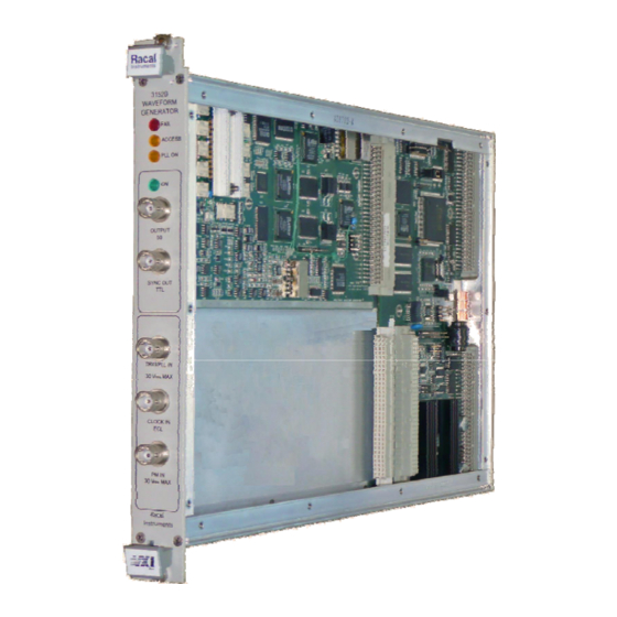
• Ultra-fast waveform downloading • Trigger delay and period-controlled auto re-trigger • Built-in counter/timer Figure 1-1, Racal Instruments 3152B EADS North America Test and Services Introduction 1-3 Artisan Technology Group - Quality Instrumentation ... Guaranteed | (888) 88-SOURCE | www.artisantg.com... -
Page 29: Arbconnection Feature Highlights
3152B User Manual Publication No. 980935 Rev. A ArbConnection (provided with the 3152B) has the following features: ArbConnection • Virtual control panels Feature • Arbitrary waveform composer Highlights • Complex pulse composer • Serial data and FM composers • Detailed virtual control panels for all functions and modes •... -
Page 30: Figure 1-3, Arbconnection Wave Composer Example
Publication No. 980935 Rev. A 3152B User Manual Figure 1-3, ArbConnection Wave Composer Example Figure 1-4, ArbConnection Pulse Composer Example EADS North America Test and Services Introduction 1-5 Artisan Technology Group - Quality Instrumentation ... Guaranteed | (888) 88-SOURCE | www.artisantg.com... -
Page 31: General Description
Description functions. The 3152B is a digital waveform generator that creates virtually any Output type of waveform. Unlike conventional function and pulse generators, the 3152B creates waveforms digitally and stores them Waveforms in memory. -
Page 32: Run Modes
The 3152B has two run modes that determine when it will output a Run Modes waveform. Continuous Run is the basic mode for generating a waveform that does not stop. This mode is appropriate except when the application requires synchronization to external events. -
Page 33: Signal Integrity
10 mVp-p to 16 Vp-p into a 50Ω load. A programmable offset shifts the output in either the positive or negative direction. As with any other VXIbus instrument, the 3152B must be used with Remote Control a host computer. All of its functions, modes, and parameters are fully programmable using one of the following three ways: •... -
Page 34: Carrier Configuration (Different Model Numbers)
• 3151B – Front panel compatible with the legacy 3151, 3151A Numbers) and 3151A+, this model is exactly the same as the 3152B, with the following exceptions: o The Phase Modulation Input BNC is replaced by a 10 MHz Reference Input BNC. -
Page 35: Specifications
Signal Amplifier module. The description in this manual ignores specific configurations and provides details of the 3152B only. The configuration chosen can have a significant impact on the way that one programs the instrument. Register based commands are parsed and executed using an external dll (3100R) but message-based commands are parsed and executed by the internal CPU (3100M). -
Page 36: Safety Considerations
Publication No. 980935 Rev. A 3152B User Manual Figure 1-6, Configurations: 3151B, 3152B, 3100R-3152B, and 3100M-3152B The 3152B has been manufactured according to international CE Safety safety standards – EN-61010. Adjustments, maintenance, or repair Considerations of the unit while the covers are removed and power is applied must be carried out only by skilled, authorized personnel. -
Page 37: Options
TRIG/PLL IN: Trigger input • CLOCK IN: An ECL level external sample clock input • REF IN: TTL level 10 MHz reference input The 3152B has five BNC connectors on its front panel, marked as follows: • OUTPUT: The main output signal •... -
Page 38: Output (Out)
Continuous mode. When placed in Trigger, (TRG/PLL) Gated, or Burst mode, the trigger input is active, and the 3152B waits for the proper condition to trigger the instrument. In Trigger and Burst modes, the TRIG/PLL input is edge-sensitive, so that a signal transition will trigger the 3152B. -
Page 39: Ext Sclk
This input accepts a 10MHz reference signal and is labeled as PM EXT 10MHz IN on the 3152B but can be programmed as either function. At the factory, this input is configured for TTL logic levels. It may be changed to 0 dBm, but only by qualified service personnel. -
Page 40: Arbitrary (User) Waveforms
Each waveform has parameters for modifying it to suit your requirements. The waveform memory can store one or more arbitrary, or user- Arbitrary (User) defined, waveforms. The regular 3152B configuration is supplied with 1 mega-sample (M-sample). A 4 M-sample waveform memory Waveforms option is available on the 3100M/R-3152B models. -
Page 41: Figure 1-8, Segment 2 - Sine Waveform
3152B User Manual Publication No. 980935 Rev. A Figure 1-7, Segment 1 – Sin (x)/x Waveform Figure 1-8, Segment 2 – Sine Waveform Figure 1-9, Segment 3 – Pulse Waveform The following sequence was made of segment 2 repeated twice, segment 1 repeated four times, and segment 3 repeated two times. -
Page 42: Modulated Waveforms
Figure 1-10, Sequenced Waveforms The use of direct digital synthesis (DDS) technology makes the Modulated 3152B is agile. During operations such as sweep, FSK, FM, and other modulation modes, the 3152B quickly synthesizes the Waveforms modulated waveform using the DDS circuit. The variety of modulated waveforms are described below. -
Page 43: Frequency Hopping
The amplitude hopping function causes the output amplitude to hop Amplitude Hopping through an amplitude list. The amount of time the 3152B dwells on an amplitude level is programmable for each hop. You may also set the dwell time uniformly over the entire hop list. -
Page 44: Digital Pulse Waveforms
You may operate the 3D function only from the ArbConnection utility. The waveform memory of the 3152B can be programmed as if it Digital Pulse were a pulse generator. All pulse parameters are adjustable,... -
Page 45: Continuous Mode
The sources to trigger a burst are the same as for the Triggered mode. The 3152B responds to a variety of trigger sources such as the Trigger Sources TRIG/PLL connector, backplane trigger lines (TTLTrg0-7), and a software trigger. -
Page 46: Modulation Run Modes
When that waveform has completed, the instrument resumes outputting non-modulated waveforms. The second option is where the 3152B, before receiving a trigger or gate, outputs a DC level. When triggered or gated, the 3152B outputs the modulated waveform. When that waveform has completed, the instrument resumes outputting a DC level. -
Page 47: Phase Modulation
The TRIG/PLL input has a programmable trigger level and programmable slope. When the 3152B is placed in PLL mode, there are two ways to Phase control the phase offset. The first way is to modify the phase offset setting using SCPI commands. -
Page 48: Programming The 3152B
Publication No. 980935 Rev. A 3152B User Manual before using the signal at the output connector. The 3152B has no front panel control; therefore, you must use a Programming the computer to communicate with the instrument. There are a number... - Page 49 3152B User Manual Publication No. 980935 Rev. A This page intentionally left blank. 1-24 Introduction EADS North America Test and Services Artisan Technology Group - Quality Instrumentation ... Guaranteed | (888) 88-SOURCE | www.artisantg.com...
-
Page 50: Chapter 2 Installation
2 as shown in Figure 2-1. Figure 2-1, Switch S1 (Set to Logical Address 2) The 3152B may be installed into any slot of the VXIbus mainframe Installation except slot 0. When inserting the instrument into the mainframe, gently rock it back and forth to seat the connectors into the backplane receptacle. -
Page 51: Controlling The Instrument From Remote
LAN Network • Download waveform data directly from an external computer without using the VXIbus controller. • Control the 3152B in a system that does not have a VXIbus slot 0 controller. 2-2 Installation EADS North America Test and Services... -
Page 52: Lan Configuration
10/100 BaseT network use (phone cables will not work). Refer interconnection issues to your network administrator. After you connect the 3152B to the LAN port, proceed to the LAN Configuration section in this chapter for instructions how to set up LAN parameters. -
Page 53: Choosing A Static Ip Address
3152B User Manual Publication No. 980935 Rev. A • Subnet mask - A code that helps the network device determine whether another device is on the same network or a different network. • Gateway IP - The IP address of a device that acts as a gateway, which is a connection between two networks. -
Page 54: Connecting To The Usb Port
Select the Ethernet adapters you are using to communicate with the Ethernet device from the drop-down list. The 3100M-3152B has a front panel USB connector that allows Connecting to the connection to a USB memory device. This USB port has only one... - Page 55 3152B User Manual Publication No. 980935 Rev. A This page was intentionally left blank. 2-6 Installation EADS North America Test and Services Artisan Technology Group - Quality Instrumentation ... Guaranteed | (888) 88-SOURCE | www.artisantg.com...
-
Page 56: Chapter 3 Operation
Chapter 3 Operation Overview This chapter explains how to operate the 3152B. Unlike a bench-top instrument, the 3152B requires a computer to turn on functions, change parameters, and configure various operating modes. Two software applications are available to control the instrument: VXIplug&play soft front panels (SFPs) and ArbConnection. -
Page 57: Output Termination
Appendix A specifies the level of protection Protection for each input or output connector. At power-up or as a result of a software reset, the 3152B changes Power On/Reset all settings to their default values. Chapter 4 lists all settings and... -
Page 58: Turning The Output On
Turns the output off outp 0 The 3152B defaults to a 1 MHz, 5 Vp-p sine wave when you apply power or reset the unit. If you turn the output on before changing any settings, the output defaults to a sine wave signal. -
Page 59: Changing The Sync Position And Width
BIT sync source, especially when the bit pulse is too narrow. It is also helpful when using the 3152B to emulate the sync pulse of another instrument that it is replacing in a test system. -
Page 60: Example: Generating A Simple Waveform
• Offset: 0 V • Amplitude: 5 V The output of the 3152B is calibrated for signals applied to a 50 Ω load. If your amplitude is twice as high as expected, then the 3152B output may not be properly terminated. In this case, either add a 50 Ω... -
Page 61: Selecting An Output Function
− (-8V to +8V peaks) Offset Amplitude-offset combinations outside the above limits will generate "settings conflict" errors. The 3152B has four basic output function types. Use the following Selecting an commands to select the waveform type: Output Function 3152B outputs... -
Page 62: Continuous Run Mode
If you have not invoked any interrupted modes since applying power to the 3152B, you may use the following command to turn off Continuous mode and default to Triggered mode: Turns off Continuous mode, changing to init:cont off an interrupted mode. -
Page 63: Re-Triggered Run Mode
This turns off Re-triggered mode. The trig:retr 0 generator will revert to the Triggered run mode. This removes the 3152B from interrupted init:cont on run mode and reverts to Continuous mode. In Gated mode, the output remains at a specific DC level until a Gated Run Mode valid event opens the gate. -
Page 64: Burst Run Mode
Each time a transition at the trigger input occurs, the 3152B generates a counted burst of output waveforms. At the end of the burst, the output assumes a DC level equal to the amplitude of the first point of the waveform. -
Page 65: Selecting The Trigger Source
• Software trigger. Your software may generate an interrupt condition by executing a trigger command. You may select (arm) only one trigger source at a time. The 3152B responds only to the selected trigger source, and ignores other sources. Use one of the following commands to select a trigger... -
Page 66: Selecting The Trigger Level
Front-panel TRIG IN connector, TTLTrg lines 0 through 7, and ECLTrg line 0. Use the following command to select slope sensitivity for trigger events: This sets the 3152B to respond to positive trig:slop pos going transitions only. Positive transitions must cross the trigger level threshold to trigger a response. -
Page 67: Using Trigger Delay
You may set the delay time in the range of 100 ns to 20 seconds in increments of 20 ns. The 3152B is programmable to drive or receive triggers on the Activating the VXIbus backplane trigger lines (TTLTrg0 through TTLTrg7). It is... -
Page 68: Example: Generating Standard Waveforms
Previous paragraphs provided sinusoidal waveform examples, Example: showing how to set amplitude and offset. This section expands on Generating that capability, covering all nine standard waveforms in the 3152B internal library: sine, triangle, square, pulse, ramp, Gaussian Standard pulses, exponential pulses, DC, and noise. -
Page 69: Generating Standard Waveforms
In a similar manner, you may use the Apply command with other standard waveforms to set some parameters while leaving others at their default values. Each standard waveform is built into the 3152B in a lookup table or Generating equation. Ten standard function shapes are available: Standard •... - Page 70 The reason for this variation is that even standard waveforms are in a manner similar to that of arbitrary waveforms, except that the 3152B stores standard waveforms in a permanent internal library for immediate use. At low frequencies, the number of points for each standard waveform is 1,000.
-
Page 71: Standard Waveform Parameters
3152B User Manual Publication No. 980935 Rev. A The built-in library of standard waveforms provides basic waveform Standard shapes. First select the basic shape, and then specify the waveform Waveform parameters to create the finished waveform to fit your requirements. -
Page 72: Generating Arbitrary Waveforms
In a similar manner, you may use the Apply command with other standard waveforms to set some parameters while leaving others at their default values. 3152B can generate arbitrary waveforms, you must first Generating Before the download them to its waveform memory. This section describes the... -
Page 73: What Are Arbitrary Waveforms
65,536. For legacy emulation, 12 bit waveform data is converted into 16 bit data with a four position shift. The standard 3152B has a waveform memory capacity of 1 M points (4 M is available as an option in some configurations). Each point has a unique address. -
Page 74: Memory Management Commands
Publication No. 980935 Rev. A 3152B User Manual Figure 3-1, ArbConnection Example of a Complex Waveform Creating Memory Segments Memory Management Segments are defined using the following command: Commands Defines segment #1 as having 2,000 trac:def 1,2000 sample points. waveform downloaded to this segment must have exactly 2,000 data points. -
Page 75: Loading Arbitrary Waveforms
Every time you download new waveform data, the waveform memory data for that segment is overwritten. The easiest way to download waveforms to the 3152B is with Loading Arbitrary ArbConnection. Using this application, you may define, create, and 3-20 Operation EADS North America Test and Services Artisan Technology Group - Quality Instrumentation ... - Page 76 This sets up the following conditions: 1) The next time you download data to the 3152B, it will go to the active segment (the 3152B will accept downloaded data only if a segment is designated as active).
-
Page 77: Selecting 12-Bit Or 16-Bit Waveform Resolution
12-bit data from legacy applications without the need to re- write the application program or data files. The default data resolution for the 3151B and 3152B is 12 bits. Other configurations, such as 3100M-3152B and 3100R-3152B, default to 16 bits. Regardless of the model number, you may set the... -
Page 78: Changing The Sample Clock Frequency
Waveform interlace is changed to 2 (waveform size must divide by 2) • Vertical resolution of arbitrary waveforms is 12 bits (3152B has 16-bit resolution). The 3152B has Legacy Compatibility mode enabled by default. For Models 3100M and 3100R, Legacy Compatibility mode is disabled by default (the full 3152B specifications apply). -
Page 79: Using The External Sample Clock Input
The 3152B does not have a single-tone sample clock source, but it provides a front-panel input, SCLK IN, that can accept a clock from an external source. -
Page 80: Generating Sequenced Waveforms
Publication No. 980935 Rev. A 3152B User Manual Sequences are comprised of waveform segments that reside in the Generating waveform memory. The sequence generator lets you link and loop Sequenced segments in a user-defined order. To avoid unexpected results, it is... -
Page 81: Sequence Commands
It is possible to have only one link in a sequence, but the output will be a continuous waveform. If only one link is specified and the 3152B is placed in Triggered advance mode, then the output will behave as it would in Burst mode, where the repeat number replaces the burst count parameter. - Page 82 Publication No. 980935 Rev. A 3152B User Manual number, segment number, loop counter, advance flag, sync flag. These parameters are explained in the Generating Sequenced Waveforms section. Using the Sequence Define command repetitively, you may program a complete definition of your sequence. When entering a...
-
Page 83: Controlling The Sequence Advance Modes
1, 2, 3, 1, 2, 3, 1, 2, 3…, with the duration of the loop depending upon the loop counter specified in the sequence table. This specifies that the 3152B idles between links seq:adv trig until it senses a valid trigger event. This mode is available only when the 3152B is in Triggered Run mode. -
Page 84: Generating
Publication No. 980935 Rev. A 3152B User Manual The modulation generator is a separate instrument within the Generating 3152B. Based on DDS technology, it has a wide dynamic range and Modulated high linearity throughout the modulation range. Waveforms The 3152B can modulate in the frequency, amplitude, and phase domains. -
Page 85: Modulation Parameters
3152B User Manual Publication No. 980935 Rev. A parameters control PSK modulation: shifted phase, baud, shift data array, and marker placement. mod:type fhop This selects the frequency hop modulation. The frequency hop sequence is created in a data table that can hold up to 5,000 frequency hops. -
Page 86: Controlling The Carrier Frequency
<value> Set the CW frequency in units of Hz. The same value will be used for all modulation functions. As explained above, the Advanced Trigger mode allows the 3152B Controlling the output to “idle” when it has finished a waveform segment and is Carrier Base Line waiting for the next trigger event. - Page 87 You can adjust the pulse characteristics only if all of its parameters can be adjusted both in the time and amplitude domain. The 3152B provides the necessary controls to do that. However, note that the pulse is generated digitally, and therefore has some limitations to observe.
-
Page 88: Pulse Design Limitations
Limitations 1. Step size determines resolution and period. The 3152B creates pulses digitally using a sample clock generator that clocks memory points. The rate of the sample clock defines the incremental resolution. For example, suppose you wish to generate pulses at a 100 ms pulse rate with 1 ms high time and the rest of the period low. -
Page 89: Using The Counter/Timer
Chapter 5 contains programming references that will allow you to program all of the half cycle parameters. You may use the 3152B as a counter/timer instrument. When using Using the this function, you may select the measurement function, gate time,... -
Page 90: Counter/Timer Limitations
Use one of the following commands to select the measurement function: Selects the frequency measurement function. coun:func freq The 3152B takes readings continuously and places them in the output queue, waiting for a read operation to clear the queue for the next reading. - Page 91 3152B User Manual Publication No. 980935 Rev. A valid trigger signal, and ends after the gate has closed. Processing time for the reading and the display is roughly 100 ms. In this mode, the counter can take a maximum of ten readings per second.
-
Page 92: Chapter 4 Arbconnection
ArbConnection application. It provides instructions for programming Chapter? instrument controls and parameters, creating waveforms, and downloading waveforms to the 3152B. ArbConnection is a utility program that aids in controlling the 3152B What Is from a remote computer. It provides three types of functions: ArbConnection? •... -
Page 93: Startup & Communication Options
ArbConnection. The purpose of this dialog box is to configure the program to communicate properly with the 3152B. For example, if you are using a GPIB device that has address 4, you may click “Specify an Address”... -
Page 94: Main Window
The Link bar is immediately below the menu bar. The Link bar provides direct access to instruments that are active on the interface bus. ArbConnection can control a number of instruments, such as the Model 3152B, simultaneously. If you connect an instrument while... - Page 95 Pushbuttons – Clicking the mouse on a pushbutton toggles an option on and off. For example, clicking the State button in the Output section turns the 3152B output on. To help indicate this, the button then appears as though pushed in, and a red bar at the center of the button appears to be illuminated.
-
Page 96: The Operation Panels
Figure 4-4, Operation Panel Selection The Operation panels provide control over the basic operation of The Operation the 3152B. From these panels, you may select the output function Panels and run mode, turn the output on and off, and adjust parameters for various functions. -
Page 97: Output
LEDs Figure 4-5, Output Panel When you click on a button, the 3152B responds immediately. When you change a numeric parameter on the display, the 3152B does not respond until you click on the Modify/Execute knob to update the instrument. - Page 98 Wave Mode The Wave Mode group is used for selecting which of the available waveforms will be generated at the output connector. The 3152B provides five types of waveforms: Standard, Arbitrary, Sequenced, Modulated, and Half Cycle. Click one of these buttons to select the waveform type.
-
Page 99: Run Mode
3152B. Figure 4-6, Run Mode Control Panel Trigger Source The 3152B accepts triggers from a number of sources: Bus, VXI Backplane (TTL Trigger 0 through 7 and ECL Trigger 1), External, and Internal. The VXI backplane trigger lines can synchronize operation with other devices residing in the VXIbus chassis. -
Page 100: Standard
TTLT0-7 – Enables one or more backplane trigger lines. Note that the 3152B can receive triggers from more than one TTLTrg line, but will not accept triggers from bus, external, or internal trigger sources. -
Page 101: Figure 4-7, Standard Waveforms Panel
Use the dial, keyboard, or the [↑] [↓} keys to adjust the reading to the required setting. After you modify the reading, click on the Modify/Execute knob to update the 3152B with the new reading. Figure 4-7, Standard Waveforms Panel... -
Page 102: Arbitrary/Sequence
Arbitrary/Sequence button on the Panels bar. Note that if you invoke the Arbitrary/Sequence Panel from the Panels menu, the 3152B will not change its output type. On the other hand, if you select the Arbitrary or Sequenced option from the Main Panel, the 3152B will immediately change its output to the selected waveform type. -
Page 103: Figure 4-8, Arbitrary & Sequence Panel
You can use the dial, keyboard, or the [↑] [↓} keys to adjust the SCLK setting. After you modify the setting, click on the Modify/Execute knob to update the 3152B with the new reading. Parameters The Parameters group contains three parameters: Amplitude, Offset, and Segment. -
Page 104: Using The Memory Partition Table
3152B waveform memory. You do not have to use the entire memory when you download a waveform. Model 3152B allows memory segmentation, so that up to 16 k smaller waveforms may be stored in this memory. There are two ways to divide the waveform memory into segments: •... -
Page 105: Figure 4-9, Memory Partition Table
The Save button saves the current session so that you may continue to configure the Memory Partition table from the same point later on. The Download button updates the 3152B with the present segment table settings. Memory... -
Page 106: Using Waveform Studio
Mapped, if file name has been assigned to the segment but the Download button has not been used yet to move the file to the 3152B memory, or Loaded, if the process has been completed by pressing either the Download button or the All (download all) button. -
Page 107: Figure 4-10, Waveform Studio
Delete – removes a highlighted segment (Download) Selection – downloads a highlighted segment only to the 3152B memory (Download) All – downloads the complete table to the 3152B memory Export – This allows exportation of Waveform Studio settings to another session Import –... -
Page 108: Figure 4-11, Sequence Table Example
This tool is called – Sequence Table. Using the Sequence table you can use waveforms that you already downloaded to the 3152B from the Segment table, link and loop in random order to create one long and complex waveform that combines the individual memory segments. - Page 109 3152B User Manual Publication No. 980935 Rev. A generator. When generating sequences, the instrument steps though the links in descending order therefore, make sure that you enter your waveform segments in exactly the order you would like them at the output.
-
Page 110: Half Cycle
Publication No. 980935 Rev. A 3152B User Manual The Half Cycle panel contains controls that select the half cycle Half Cycle functions and adjust the half cycle parameters. The half cycle functions are generated with variable and controllable delay between the halves. If triggered mode, one half at a time is generated as a result of a trigger signal regardless of the programmed delay value. -
Page 111: Figure 4-13, Modulation Panels
3152B User Manual Publication No. 980935 Rev. A selected, the instrument generates the unmodulated carrier frequency (CW) until a valid signal is applied. When the second option is selected, the instrument generates a DC level signal until stimulated to generate a modulation cycle. The modulation options, their associated parameters, and the various run mode options are described separately for each of the panels below. -
Page 112: Figure 4-14, Fm Panel
You can use the dial, keyboard, or the [↑] [↓} keys to adjust the readout to the required setting. After you modify the reading, click on the Modify/Execute knob to update the 3152B with the new setting. EADS North America Test and Services ArbConnection 4-21 Artisan Technology Group - Quality Instrumentation ... -
Page 113: Figure 4-15, Am Panel
3152B User Manual Publication No. 980935 Rev. A The AM panel (Figure 4-15) contains parameters for controlling the amplitude modulation function. To turn the AM function on and off, click on the AM button in the State group. The various groups in the AM panel are described below. -
Page 114: Sweep
You can use the dial, keyboard, or the [↑] [↓} keys to adjust the readout to the required setting. After you modify the reading, click on the Modify/Execute knob to update the 3152B with the new setting. The Sweep Modulation panel (Figure 4-16) contains parameters for Sweep controlling the sweep function. -
Page 115: Fsk/Psk/Ask
[↑] [↓] keys to adjust the readout to the required setting. After you modify the reading, click on the Modify/Execute knob to update the 3152B with the new setting. The FSK/PSK/ASK panel (Figure 4-17) contains parameters for FSK/PSK/ASK controlling the shift keying modulation functions. -
Page 116: Figure 4-17, Fsk/Psk/Ask Modulation Panel
Publication No. 980935 Rev. A 3152B User Manual Baseline – Baseline parameter affects output characteristics in one of the interrupted run modes (i.e., triggered, burst). In this case this parameter defines where the signal idles between triggers. There are two options: CW and DC. The DC... - Page 117 You can use the dial, keyboard, or the [↑] [↓} keys to adjust the readout to the required setting. After you modify the reading, click on the Modify/Execute knob to update the 3152B with the new reading.
-
Page 118: Ampl/Freq Hop
Publication No. 980935 Rev. A 3152B User Manual marker output. The Ampl/Freq Hop panel (Figure 4-18), contains parameters for Ampl/Freq Hop controlling the hop modulation function. To turn one of the functions on and off, click on the appropriate button in the State group. -
Page 119: Figure 4-18, Amp/Freq Hop Panel
You can use the dial, keyboard, or the [↑] [↓} keys to adjust the readout to the required setting. After you modify the reading, click on the Modify/Execute knob to update the 3152B with the new setting. -
Page 120: Auxiliary Panels
3152B are purged. Measurement Function The measurement function group has control to select the measurement function for the counter/timer operation. The 3152B can measure the following function: Frequency, Period, Period Averaged, Pulse Width, and Totalize. The totalize function has two options. -
Page 121: Pulse Generator
3152B User Manual Publication No. 980935 Rev. A Figure 4-20, Counter/Timer Panel Display The Display Group has controls to select the display mode and to select if the display shows measurement or gate time readings. In normal mode, the counter is armed to receive signal at the trigger input. -
Page 122: X-Instrument Sync
State The State Group has a control to enable or disable the pulse generator function. Note that when the pulse generator function is enabled, all other waveform generation features of the 3152B are disabled. Pulse Mode The Pulse Mode group has controls to toggle between single and double pulse modes. -
Page 123: Figure 4-22, X-Instrument Synchronization Pool List
First, notice the variety of instruments that are listed in the Instruments Pool. Actually, they all are the same 3152B units except they are mounted on different platforms for various applications. The 3100-3152B is comprised of a single 3152B and the 3100-3152B-3152B has two 3152B embedded in the same module. - Page 124 Chan (Channel) – this field is relevant for the 3100-3152B-3152B model which has two 3152B units installed in a single VXI slot. In this case, each instrument operates as a stand-alone generator but also can be configured as a dual-channel instrument.
-
Page 125: Figure 4-23, Adjacent Synchronization Between Two Instruments
3152B User Manual Publication No. 980935 Rev. A module and its servants. Note that the master instrument can also be set with an offset but then the final offset between modules will be the difference between the offset settings of the salves to the master. -
Page 126: Figure 4-25, Eclt Synchronization Example
Publication No. 980935 Rev. A 3152B User Manual Figure 4-25, ECLT Synchronization Example So far, the X-Instruments Synchronization fields were discussed and described. The following describes the functions of the buttons. Clear All Assignments – used to completely reset the table. Note that only editable fields are affected by this action. -
Page 127: The System Panels
3152B User Manual Publication No. 980935 Rev. A The System tab (Figure 4-26) provides access to a group of panels The System Panels that control some general system parameters and provides access to calibration. There are two panels in this group: General/System, which provides access to some system commands, utilities and filters;... -
Page 128: Figure 4-27, General/Filters Panel
A list of factory defaults is given in Chapter 5. Query Error – queries the 3152B for programming errors. This command is normally not necessary because ArbConnection won’t generate settings conflicts or syntax erorrs. But, when sending SCPI commands to the instrument using the Command Editor, errors can be generated. -
Page 129: Calibration
3152B User Manual Publication No. 980935 Rev. A The Calibration panel (Figure 4-28) provides access to remote Calibration calibration. To access the remote calibration panel, you will need to have a valid User Name and Password. Proper training is required to perform calibration. -
Page 130: The Wave Composer
Publication No. 980935 Rev. A 3152B User Manual Figure 4-29, Composers Panel Because the 3152B is an arbitrary waveform generator, it has to be The Wave loaded with waveform data before it can start generating Composer waveforms. The waveform generation and editing utility is part of ArbConnection and is called the Wave Composer. -
Page 131: File Menu
3152B User Manual Publication No. 980935 Rev. A Figure 4-30, Wave Composer Opening Screen The File menu has four selections that control waveform file File Menu operations. This menu also can be used to print the active waveform or to exit from Wave Composer. Descriptions of the menu selections from the File pull-down menu are given below. -
Page 132: Edit Menu
Publication No. 980935 Rev. A 3152B User Manual your waveform. It will let you select a name, location and format for your waveform file. Print Lets you print the active waveform graph The standard printer dialog box will appear and will let you setup the printer and print the waveform graph. -
Page 133: View Commands
3152B User Manual Publication No. 980935 Rev. A Filter The Filter operation is calculated using a moving average. This is done by recalculating each point as an average of a number of symmetrical points adjacent to each point. You can filter the entire... -
Page 134: Wave Menu
Publication No. 980935 Rev. A 3152B User Manual below. Zoom In The Zoom In operation operates between anchors. Anchors are shown as left pointing and right pointing triangles. The default position of the anchors is the start and the end of the waveform. To move an anchor to a new location, drag the anchor to the left or right as required. - Page 135 3152B User Manual Publication No. 980935 Rev. A open a dialog box. An example of the Sine waveform dialog box is shown in Figure 4-33. This dialog box is similar to the rest of the waveforms, so the other waveform dialog boxes will not be described here.
-
Page 136: The Toolbar
The vertical axis represents 12-bits (4k levels) of resolution with 3152B legacy mode selected or 16-bits (64k levels) of vertical resolution when modern mode operation is selected. The horizontal axis, by default has 1024 points (from point 0 to 1023). -
Page 137: Figure 4-35, Waveform Screen
3152B User Manual Publication No. 980935 Rev. A in your instrument. The wave composer will let you define the horizontal axis to a maximum of 1 Meg words with standard 1MB memory and 4 Meg words with the 4MB memory expansion option (where available). -
Page 138: Generating Waveforms Using Equation Editor
Publication No. 980935 Rev. A 3152B User Manual waveform file will be displayed in Wave Composer’s title bar, including the path. A more general purpose way to create waveforms using Generating ArbConnection is to use Equation Editor. Equation Editor let you... - Page 139 3152B User Manual Publication No. 980935 Rev. A operations is given later. Max – defines the positive peak of the vertical axis Min – defines the negative peak of the vertical axis Cycles The Cycles parameter defines how many waveform cycles will be created within the specified start and end anchor points.
-
Page 140: Writing Equations
In reality, the 3152B generates its waveforms exactly as shown on the screen but, if the waveform has many horizontal points, the steps get smaller and harder to see without magnification. -
Page 141: Typing Equations
3152B User Manual Publication No. 980935 Rev. A pi (π) Circumference of unit-diameter circle Horizontal wavelength in points I/per omg (ω) 2*π*f Amplitude in units of points or Hertz sin(x) The sine of x* cos(x) The cosine of x* tan(x) -
Page 142: Equation Examples
Publication No. 980935 Rev. A 3152B User Manual sinewave. So what's wrong? Well, if you'll give it a little amplitude it might help so, do it now exactly as follows: Amplitude(p)=8000*sin(omg*p) There you go. You should now see a perfect sine waveform with a period of 1000 points. -
Page 143: Figure 4-38, Using The Equation Editor To Modulate Sine Waveforms
3152B User Manual Publication No. 980935 Rev. A Figure 4-38, Using the Equation Editor to Modulate Sine Waveforms. In the following example, 20% second harmonic distortion has been added to a standard sinewave. The original waveform had a peak- to-peak value of 24000 points so 19% second harmonic is equivalent to 4500 points. -
Page 144: Figure 4-39, Using Equation Editor To Add Second Harmonic Distortion
Publication No. 980935 Rev. A 3152B User Manual Figure 4-39, Using Equation Editor to Add Second Harmonic Distortion. In Figure 4-40 we created 10 cycles of sinewave made to decay exponentially. The original expression for a standard sinewave is multiplied by the term e^(p/-250). Increasing the value of the divisor (200 in this case) will slow down the rate of decay. -
Page 145: Figure 4-40, Using The Equation Editor To Generate Exponentially Decaying Sinewave
3152B User Manual Publication No. 980935 Rev. A Figure 4-40, Using the Equation Editor to Generate Exponentially Decaying Sinewave The last example as shown in Figure 4-41 is the most complex to be discussed here. Here, 100 cycles of a sine wave are amplitude modulated with 10 cycles of sine wave with a modulation depth of 20%. -
Page 146: Combining Waveforms
Publication No. 980935 Rev. A 3152B User Manual Figure 4-41, Using Equation Editor to Build Amplitude Modulated Signal with Sidebands Combining The last feature to be described here allows you to combine waveforms which were previously stored in a file. You can write... -
Page 147: Figure 4-42, Combining Waveforms Into Equations
3152B User Manual Publication No. 980935 Rev. A noise signal. From the File menu select Save Waveform As… and save this waveform into the default folder using the name Noise.wav. Step 3 – Write and compute the original equation: Amplitude(p)= Sine.wav*sin(omg*p*5)+Noise.wav/10 Press [Preview] and [Accept] and the waveform graph should look like Figure 4-42. -
Page 148: The Pulse Composer
“Force pulse to one segment” option and the 3152B will do some extra “muscle flexing” to fit the pulse as required. To launch the Pulse Composer point and click on the Pulse tab in the Panels bar. -
Page 149: Figure 4-43, Pulse Composer Screen
3152B User Manual Publication No. 980935 Rev. A Open… The Open… (Ctrl+O) menu item lets you choose a previously saved pulse file and load it to the Pulse Composer graph. The *.PLS file extension, which is a text format, is supported by this operation. -
Page 150: Edit Menu
Publication No. 980935 Rev. A 3152B User Manual takes you back to the Panels screen. If you made changes to your pulse since it was last saved, the Pulse Composer will prompt you to Save or Abandon changes these changes. -
Page 151: Figure 4-44, Pulse Editor
3152B User Manual Publication No. 980935 Rev. A sections of the pulse train. Eventually, when all pulse sections have been designed, the entire pulse train as shown when the Full Train option has been selected will be downloaded to the instrument as a single waveform. -
Page 152: Tools Menu
Note The Clear Memory command affects the entire waveform memory of the 3152B. Be careful not to erase memory segments that you need to use and that haven’t already been backed up. The Pulse Composer toolbar (Figure 4-46) contains icons for editing... -
Page 153: Figure 4-47, Complete Pulse Train Design
3152B User Manual Publication No. 980935 Rev. A pulse trains, the full train can be divided to smaller sections with each section designed separately. Figure 4-47 shows a complex pulse train which was made from five simpler sections and Figure 4- 48 shows the design of the fifth section only of the pulse train. -
Page 154: Setting The Pulse Editor Options
There are three options in the mode of operation group: Freely Select Mode of Operation - use this mode of operation to let the generator decide for itself how to create pulses in 3152B waveform memory. Force Pulse Train to Single Segment - recommended if you are using one pulse section only. -
Page 155: Using The Pulse Editor
The longer the transition time, the more steps the program will need to smooth the transition. Allow System Control – Lets the 3152B decide how to make the transitions efficient in terms of memory usage and slope smoothness. -
Page 156: Figure 4-50, Using The Pulse Editor
Publication No. 980935 Rev. A 3152B User Manual Figure 4-50, Using the Pulse Editor The Pulse Editor has four groups: Section Structure, Pulse Train Design Format, Section Properties, and control buttons. These groups are described below. Pulse Train Design Format There are two methods (or formats) that can be use for designing the pulse shape: DC Intervals and Time/Level Points. - Page 157 3152B User Manual Publication No. 980935 Rev. A Index = 4, Level = 0, Time interval = 0.1, (Cumulative Time = 0.6) Index = 5, Level = 0, Time interval = 0.4, (Cumulative Time = 1.0) Note that as you build the segments that the pulse is being drawn on the screen as you type in the parameters and the specified point is marked with a red dot.
-
Page 158: Pulse Example, Section 2
Publication No. 980935 Rev. A 3152B User Manual Now that we are familiar with the Pulse Composer and its operation, Pulse Example, we are ready to start building the first section of the pulse as shown Section 1 in Figure 4-47. Point and click on the New icon and open the Pulse Editor. -
Page 159: Pulse Example, Section 3
3152B User Manual Publication No. 980935 Rev. A The first pulse section is complete. We are ready now to start Pulse Example, building the second section of the pulse as shown in Figure 4-48. Section 2 Use the Pulse Composer’s Edit menu to select the Append Section operation. -
Page 160: Pulse Example, Section 4
Publication No. 980935 Rev. A 3152B User Manual The second pulse section is now complete. We are ready now to Pulse Example, start building the third section of the pulse as shown in Figure 4-49. Section 3 Use the Edit menu to select the Append Section operation. A new section number will appear but its fields will be initially empty to the right of the section identifier. -
Page 161: Pulse Example, Section 5
3152B User Manual Publication No. 980935 Rev. A The third pulse section is now complete. We are ready now to start Pulse Example, building the forth section of the pulse as shown in Figure 4-50. Use Section 4 the Edit menu to select the Append Section operation. A new section number will appear but its fields will be initially empty to the right of the section identifier. -
Page 162: Downloading The Pulse Train
Publication No. 980935 Rev. A 3152B User Manual the right of the section identifier. Note that there are fast transitions required for this section that will start from the last point of the previous section and will connect to the start point of the next section. Therefore, select the Time/Level Points option in the Pulse Train Design Format. -
Page 163: Interpreting The Download Summary
Pulse Composer, the parameters and mode of Download Summary operation of the 3152B might be altered. The download summary shows what the new mode of operation will be so that you can reject the new settings if you do not agree to the changes. Once... -
Page 164: The Fm Composer
The FM composer is a great tool for controlling frequency agility by generating the agility curve as an arbitrary waveform. For example, if you create a sine waveform, the 3152B will generate frequency- modulated signal that will follow the sine pattern. The resolution and accuracy of the modulated waveform is unsurpassed and can only be duplicated by mathematical simulation. -
Page 165: File Menu
3152B User Manual Publication No. 980935 Rev. A The File menu has 4 menu selections which that control waveform File Menu file I/O operations. Also use this menu to print the waveform or to exit the FM Composer program. Description of the various commands under File is given below. -
Page 166: Figure 4-58, Generating Sine Modulation Using The Fm Composer
Publication No. 980935 Rev. A 3152B User Manual Creating Sine Waveforms Use the following procedure to create sine waveforms from the built-in library. Click on Wave, then sine… The dialog box shown in Figure 4-54 appears. You can now start programming parameters that are available in this box. -
Page 167: The 3D Composer
3152B User Manual Publication No. 980935 Rev. A Cycles – The Cycles parameter defines how many sine cycles will be created within the specified start and end anchor points. The example below shows three sine cycles. Start Phase – The start phase parameter defines the angle at which the sine will start. -
Page 168: Shared Horizontal Controls
Publication No. 980935 Rev. A 3152B User Manual Figure 4-59, 3D Composer Screen The 3D composer has three main sections: Shared horizontal Controls, Vertical Controls and Graphical Screens. The panels on the left are used for designing the waveform parameters and the screens on the right side depict the shape of the profile. -
Page 169: Figure 4-60, Parameters Tab
3152B User Manual Publication No. 980935 Rev. A Parameters The Parameters tab, as shown in Figure 4-56, is used for setting up the duration of the signal, the position of the marker (if required) and the amount of memory that is allocated for this purpose. Setting up correctly the parameters in this group is the basic and the most important task before you start designing 3D waveforms. -
Page 170: Vertical Controls
Publication No. 980935 Rev. A 3152B User Manual the following relationship: Duration = Modulation SCLK / Wavelength Each of the parameters has a finite length and therefore, the duration has maximum and minimum intervals. The modulation SCLK has a range of 1 Hz to 2.5 MHz and the Wavelength is limited from 2 points to 30,000 points. -
Page 171: Graphical Screens
3152B User Manual Publication No. 980935 Rev. A Figure 4-62, 3D Vertical Controls The 3D Waveform Graphs are shown in Figure 4-59. You can not Graphical Screens change anything on the screens. However, anything that you design in the Vertical Controls fields will automatically be updated and displayed on the graphical screens. -
Page 172: Designing 3D Profiles
Publication No. 980935 Rev. A 3152B User Manual Figure 4-63, 3D Waveform Graphs 3D profiles are designed in the Vertical Controls fields. Notice that Designing 3D there are three separate control fields: Amplitude, Frequency and profiles Phase. Always start the design from the Shared Horizontal Controls group. -
Page 173: Figure 4-64, 3D Chirp Design Example
3152B User Manual Publication No. 980935 Rev. A Figure 4-64, 3D Chirp Design Example 4-82 ArbConnection EADS North America Test and Services Artisan Technology Group - Quality Instrumentation ... Guaranteed | (888) 88-SOURCE | www.artisantg.com... -
Page 174: The Command Editor
3152B User Manual The Command Editor is a tool for doing low-level programming of The Command the 3152B. Invoke the Command Editor from the System menu at Editor the top of the screen. The Command Editor dialog box, as shown in Figure 4-61, will pop up. -
Page 175: Figure 4-66, Log File Example
3152B User Manual Publication No. 980935 Rev. A Figure 4-66, Log File Example 4-84 ArbConnection EADS North America Test and Services Artisan Technology Group - Quality Instrumentation ... Guaranteed | (888) 88-SOURCE | www.artisantg.com... -
Page 176: Chapter 5 Programming Reference
3152B as a legacy replacement is given in Table 5-1. A complete listing of all commands used for programming the 3152B in modern mode or the 3100M models (in default mode) is given in Table 5-2. -
Page 177: Command Format
3152B User Manual Publication No. 980935 Rev. A OUTPut is the root keyword of the command; FILTer and STATe are second level keywords. LPASs is third level keyword. A colon ( : ) separates a command keyword from a lower level keyword. -
Page 178: Querying Parameter Setting
3152B User Manual Publication No. 980935 Rev. A Parameters FREQuency {<frequency>|MINimum|MAXimum} Instead of selecting a specific frequency, substitute MIN to set the frequency to its minimum value or MAX to set the frequency to its maximum value. Query the current value of most parameters by adding a question Querying mark ( ? ) to the command. -
Page 179: Discrete Parameters
Arbitrary block parameters are used for loading waveforms into the Arbitrary Block generator's memory. Depending on which option is installed, the Parameters 3152B can accept binary blocks up to 1M bytes. The following command uses an arbitrary block parameter that is loaded as binary data: TRAC:DATA#564000<binary_block>... -
Page 180: Alternative Command Set (Hs Commands)
SCPI parsers that are flexible in the way that characters are sent, the HS mode rejects additional spaces and characters and issues error codes. For example, the command to turn off the output of the 3152B is: OUTP ON HS command syntax for the same command is:... -
Page 181: Rules For Using Hs Command Mode
3152B User Manual Publication No. 980935 Rev. A command INSTrument:MODE FAST. In HS mode, the instrument accepts HS commands only. SCPI commands sent when the 3152A is in HS mode will generate errors. Likewise, in NORMal (SCPI) mode, HS commands will not be accepted. -
Page 182: Legacy Vs. Modern Command Set
3152B User Manual Publication No. 980935 Rev. A For users of the 3151B or 3152B models, the instrument defaults to Legacy vs. legacy 3152A-compatible mode. The SCPI commands that are Modern shown in Table 5-1 list the legacy 3152A command set and indicate where the 3152B command differs. -
Page 183: 3152B Legacy Commands
3152B User Manual Publication No. 980935 Rev. A The 3152B is a modern and updated version of the Model 3152A 3152B Legacy employing the latest technology and component improvements. Commands Although 100% backwards compatibility was the basis for the new 3152B design, some of the 3152A functionality could not be duplicated exactly. - Page 184 3152B User Manual Publication No. 980935 Rev. A Table 5-1, 3152B SCPI Command Summary for 3152A Emulation (continued) Keyword Parameter Form Default 3152A Output Control Commands :OUTPut :SHUNt OFF | ON | 0 | 1 Error, not supported 0250A :ECLTrg<n>...
-
Page 185: Table 5-2, 3152B Scpi Command Summary
3152B User Manual Publication No. 980935 Rev. A Table 5-1, 3152B SCPI Command Summary for 3152A Emulation (continued) Keyword Parameter Form Default 3152A Standard Waveforms Commands [:SOURce] :SHAPe SINusoid | TRIangle | SQUare | PULSe | RAMP | SINC |... - Page 186 3152B User Manual Publication No. 980935 Rev. A Table 5-1, 3152B SCPI Command Summary for 3152A Emulation (continued) Keyword Parameter Form Default 3152A Arbitrary Waveforms Commands :FORMat :WAVE NORMal | USER Error, not supported 0100A :RESolution 12BIT | 16BIT 12BIT...
- Page 187 3152B User Manual Publication No. 980935 Rev. A Table 5-1, 3152B SCPI Command Summary for 3152A Emulation (continued) Keyword Parameter Form Default 3152A Modulated Waveforms Commands [:SOURce] :INTernal :FREQuency 10e-3 to 1e6 0781A :DEPTh 0 to 100 0780A :EXEcute 07820...
-
Page 188: 3100R/M-3152B Commands
*STB? 1508@? *TST? 1500@? As explained in Chapter 1, one or two 3152B’s can be installed in a 3100R/M-3152B 3100R or a 3100M carrier. If you purchased this version then you Commands probably did not intend to use the 3152B as a replacement for a 3152A legacy program and hence the commands set is much broader and allows access to the entire functionality of the 3152B. - Page 189 3152B User Manual Publication No. 980935 Rev. A Table 5-2, 3152B SCPI Command Summary Keyword Parameter Form Default 3152A Instrument Control Commands :INSTrument :MODE NORMal | FAST NORM 0150A [:SELect] 1 | 2 0008A :COUPle :MODE MASTer | SLAVe MAST...
- Page 190 3152B User Manual Publication No. 980935 Rev. A Table 5-2, 3152B SCPI Command Summary (continued) Keyword Parameter Form Default 3152A Output Control Commands :OUTPut :SHUNt OFF | ON | 0 | 1 Error, not 0250A supported :ECLTrg<n> <n> = 0 to 1...
- Page 191 :SEGMent [:DATA] <data_array> 10501# (*) For Backwards compatibility, 3152B defaults to 12BIT; 3100M/R defaults to 16BIT (**) 3152B defaults to LEG; 3100M/R defaults to MOD 5-16 Programming Reference EADS North America Test and Services Artisan Technology Group - Quality Instrumentation ... Guaranteed | (888) 88-SOURCE | www.artisantg.com...
- Page 192 3152B User Manual Publication No. 980935 Rev. A Table 5-2, 3152B SCPI Command Summary (continued) Keyword Parameter Form Default 3152A Apply Commands [:SOURce] :APPLy FREQ,AMPL,OFFS 0300C :SINusoid FREQ,AMPL,OFFS,PHAS,POW 0301E :TRIangle FREQ,AMPL,OFFS,PHAS,POW 0302E :SQUare SQU,FREQ,AMPL,OFFS,DCY 0303D :PULSe FREQ,AMPL,OFFS,DEL,WID,LEE,TRE 0304G :RAMP FREQ,AMPL,OFFS,DEL,LEE,TRE...
- Page 193 3152B User Manual Publication No. 980935 Rev. A Table 5-2, 3152B SCPI Command Summary (continued) Keyword Parameter Form Default 3152A Modulated Waveforms Commands (continued) [:SOURce] :FUNCtion :SHAPe SINusoid | TRIangle | SQUare | RAMP 0057A :INTernal :FREQuency 10e-3 to 1e6...
- Page 194 3152B User Manual Publication No. 980935 Rev. A Table 5-2, 3152B SCPI Command Summary (continued) Keyword Parameter Form Default 3152A Modulated Waveforms Commands (continued) [:SOURce] :ASK [:AMPLitude] [:STARt] 0 to 16 0064A :SHIFted 0 to 16 0065A :BAUD 1 to 10e6...
- Page 195 3152B User Manual Publication No. 980935 Rev. A Table 5-2, 3152B SCPI Command Summary (continued) Keyword Parameter Form Default 3152A Digital Pulse Commands :DPULse :DELay 0 to 10 0143A :DOUBle [:STATe] OFF | ON | 0 | 1 0144A :DELay...
- Page 196 3152B User Manual Publication No. 980935 Rev. A Table 5-2, 3152B SCPI Command Summary (continued) Keyword Parameter Form Default 3152A Synchronization Commands (continued) [:SOURce] :PHASe2 (=PLL) :LOCK [:STATe] OFF | ON | 0 | 1 0920A :SOURce EXTernal | TTLTrg<n> | ECLTrg 0...
- Page 197 3152B User Manual Publication No. 980935 Rev. A Table 5-2, 3152B SCPI Command Summary (continued) Keyword Parameter Form Default 3152A System Commands (continued) *CLS 15000 *ESE 1 to 255 1501A *OPC 15020 *RST 14200 *SRE 1 to 255 1503@? *TRG...
-
Page 198: Instrument & Output Control Commands
Factory defaults after *RST are shown in the Default column. Parameter range and low and high limits are listed, where applicable. The 3152A column shows where 3152B commands are backward- compatible with the older 3152A design. Table 5-3, Instrument & Output Control Commands Summary... - Page 199 3152B User Manual Publication No. 980935 Rev. A Table 5-3, Instrument & Output Control Commands Summary (Continued) Keyword Parameter Form Default 3152A [:SOURce] :ROSCillator :SOURce INTernal | EXTernal | CLK10 0028A :FREQuency :EXTernal? 0420@? [:CW] 10e-3 to 100e6 | MINimum | MAXimum...
- Page 200 INSTrument:MODE {NORMal|FAST}(?) HS Syntax: 0150A0(?) Description Use this command to modify the 3152B to accept HS commands. Use INST:MODE FAST to program the instrument with HS commands; Use 0150A0 to restore the instrument to accept normal SCPI commands. Name Type...
- Page 201 3152B User Manual Publication No. 980935 Rev. A designated as master. Response The 3152B returns MAST or SLAV depending on the current instrument coupling mode assignment. INSTrument:COUPle:DELay <delay>(?) HS Syntax: 0003A<float>(?) Description Programs the delay time between the master and slave instruments. The waveform start on the slave unit is delayed with respect to the start of the master.
- Page 202 To select the master instrument use the INST:SEL 1 command. Response The 3152B returns 1 if the coupled state is on or 0 if the couple state is off. EADS North America Test and Services Programming Reference 5-27...
- Page 203 Although the original purpose of these lines was to be used as ECL triggers to other instruments, the 3152B uses these lines to synchronize clocks and start signals with other instruments in the chassis. The ECLTRG lines run in parallel from slot to slot so it is not important where the receiving module is placed inside the chassis, as long as the receiving instrument assigns the same lines as inputs.
- Page 204 OUTPut {OFF|ON|0|1}(?) HS Syntax: 0200A<0|1>(?) Description This command toggles the 3152B output relay. Note that for safety, the outputs always defaults to off, even if the last instrument setting before power down was on. Parameters Range Type...
- Page 205 Default Description Discrete Toggles the SYNC output between on and off. Response The 3152B returns 1 if the SYNC output is on or 0 if the SYNC output is off. OUTPut:SYNC:POSition<position>(?) HS Syntax: 0242A<long>(?) Description Programs the 3152B SYNC position.
- Page 206 (below 0 V) and changes to high when the output level becomes positive (above 0 V). Response The 3152B returns BIT, LCOM, SSYN, HCL, PULS, or ZERO depending on the selected SYNC source. OUTPut:SYNC:WIDTh <width>(?) HS Syntax: 0243A<integer>(?) Description Programs the 3152B SYNC position.
- Page 207 “n” designates the length of the segment. Response The 3152B returns the current SYNC width value. OUTPut:TRIGger:SOURce {BIT|LCOM|SSYN|HCL|PULS|ZERO|INTernal| EXTernal}(?) Description The TTLTRG signals, when enabled and placed on the backplane, can be asserted with signals coming from a number of sources.
- Page 208 Response The 3152B returns n,0 when a specific backplane trigger line is off or n,1 when a specific backplane trigger line is enabled. The trigger line <n> can range from 0 to 7. ROSCillator:SOURce {INTernal|EXTernal|CLK10}(?) Description This command selects the reference source for the sample clock generator.
- Page 209 Publication No. 980935 Rev. A Response The 3152B measures and returns the current frequency applied to the trig/pll input. If no signal is applied to the trigger input, the response will be 0. The returned value will be in scientific notation(for example: 100mHz would be returned as 100e-3.
- Page 210 Discrete Sets the amplitude to the highest possible level (16V). Response The 3152B returns the current amplitude value. The returned value will be in scientific notation, e.g., 100 mV EADS North America Test and Services Programming Reference 5-35 Artisan Technology Group - Quality Instrumentation ... Guaranteed | (888) 88-SOURCE | www.artisantg.com...
- Page 211 Offset and amplitude settings are independent providing that the offset + amplitude do not exceed the specified window. Response The 3152B returns the current offset value. The returned value will be in scientific notation, e.g., 100 mV would be 100e-3. PHASe:OFFSet <phase_offs>(?) HS Syntax: 0027A<float>(?) Description This command will affect a slave instrument only when it is synchronized to another module in the chassis.
-
Page 212: Run Mode Commands
3152B are purged and the 3152B is transformed to behave as if it was a stand-alone counter/timer. Response The 3152B returns FIX, USER, SEQ, SWE, MOD, HALF, or COUN depending on the current 3152B operating mode. The Run Mode Commands group is used to synchronize device Run Mode actions with external events. - Page 213 HS Syntax: 11000 Description Use this command to send a software trigger to the 3152B. The *trg command has the same effect. This command will affect the 3152B while it is running in interrupted run mode (INIT:CONT 0) and only when the selected trigger source is BUS.
- Page 214 3152B User Manual Publication No. 980935 Rev. A TRIGger:BURSt {OFF|ON|0|1}(?) HS Syntax: 1120A<0|1>(?) Description This command toggles counted burst run mode on and off. This command affects the 3152B when it is in INIT:CONT 0 mode. Parameters Range Type Default...
- Page 215 Note that if you want to control the trigger level threshold, you can only do it if you are using the front panel input. This command affects the 3152B only after it is set to INIT:CONT OFF mode.
- Page 216 The 3152B returns LEV or TRAN depending on the selected option. TRIGger:GATE {OFF|ON|0|1}(?) HS Syntax: 1150A<0|1>(?) Description Toggle gated run mode on or off. Affect the 3152B only after it is set to INIT:CONT OFF mode. Parameters Range Type Default...
- Page 217 HS Syntax: 0187A<0|1>(?) Description Toggles the state of the re-trigger function. The re-trigger feature causes the 3152B to self-trigger at the end of a triggered signal cycle. This differs from internally triggered mode in that the internal trigger timer starts the waveform at a periodic interval and the re-trigger feature re-triggers the waveform after a delay which begins at the end of the waveform cycle.
-
Page 218: Standard Waveform Control Commands
Description Discrete Toggles re-trigger mode. Response The 3152B returns 0 or 1 depending on the selected option. RETRigger:TIMe <time>(?) HS Syntax: 0161A<float>(?) Description Specifies the amount of time between the end of a waveform cycle and the beginning of the next waveform cycle. -
Page 219: Table 5-5, Standard Waveforms Control Commands Summary
-100 to 100 0770A :AMPLitude -8 to 8 0046A FUNCtion:SHAPe {SINusoid|TRIangle|SQUare|PULSe|RAMP|SINC| GAUSsian|EXPonential|DC|NOISe}(?) HS Syntax: 0600A<0|1|2|3|4|5|6|7|8|9>(?) Description Defines the standard waveform shape to be output by the 3152B. Parameters Name Type Default Description SINusoid Discrete Selects the built-in sine waveform. TRIangle Discrete Selects the built-in triangular waveform. - Page 220 Selects the built-in DC waveform. NOISe Discrete Selects the built-in noise waveform. Response The 3152B returns SIN, TRI, SQU, SPUL, RAMP, SINC, GAUS, EXP, DC, or NOIS depending on the current 3152B setting. SINusoid:PHASe <phase>(?) HS Syntax: 0700A<float>(?) Description Programs the start phase for the standard sine waveform. This command has no affect on modulated waveforms.
- Page 221 Programs the square wave duty cycle parameter in units of percent (ratio of on-time to off-time). Response The 3152B returns the current duty cycle value for the square wave function. 5-46 Programming Reference EADS North America Test and Services Artisan Technology Group - Quality Instrumentation ... Guaranteed | (888) 88-SOURCE | www.artisantg.com...
- Page 222 <delay> 0 to Numeric Programs the pulse delay parameter in units of percent. 99.999 Response The 3152B returns the current pulse delay value. PULSe:WIDth <pulse_width>(?) HS Syntax: 0731A<float>(?) Description Programs pulse high portion of the standard pulse waveform. Parameters Name...
- Page 223 Numeric Programs the pulse fall time parameter in units of 99.999 percent. Response The 3152B returns the current fall time value for the pulse function. RAMP:DELay <delay>(?) HS Syntax: 0740A<float>(?) Description Programs ramp start delay for the standard ramp waveform.
- Page 224 <exp> 1 to 200 Numeric Programs the exponent parameter for the Gaussian function. Response The 3152B returns the current exponent value for the Gaussian function. EXPonential:EXPonent <exp>(?) HS Syntax: 0760A<integer>(?) Description Programs the exponent for the standard exponential waveform. Parameters...
-
Page 225: Arbitrary Waveforms Control Commands
Each data point has a vertical resolution of 16 bits (65536 points), i.e., each sample is placed on the vertical axis with a precision of 1/65536. The 3152B has the following waveform memory capacity: 1M –... -
Page 226: Table 5-6, Arbitrary Waveforms Commands Summary
Description This selects between 12-bit or 16-bit waveform formats. 16-bits is the default resolution for the 3100M and 12-bits is the default resolution for the 3151B and 3152B for compatibility with legacy models. Parameters EADS North America Test and Services Programming Reference 5-51 Artisan Technology Group - Quality Instrumentation ... - Page 227 HS Syntax: 0189A<0|1> Description Toggles between legacy and modern operation of the 3152B. Legacy implies that the 3152B behaves exactly like the 3152A for backward compatibility. This automatically modifies certain parameters to duplicate the 3152A limits. For example: maximum sample clock frequency is limited to 100 MS/s; waveform interlace is changed to 2, and;...
-
Page 228: Figure 5-1, Definite Length Arbitrary Block Data Format
Figure 5-2 shows a waveform word that is acceptable for the 3152B. There are a number of points you should be aware of before you start preparing the data: 1. -
Page 229: Figure 5-2, 3152B 16-Bit Waveform Data Point Representation
0x0000 correspond to -8 V and 0xFFFF corresponds to +8V (0xFFF corresponds to +8 V for 3152A emulation). 3. 3152B data point data point 65,535 corresponds to full-scale amplitude setting. Point 32768 (point 2048 for the legacy 3152A) corresponds to the 0 V amplitude setting. - Page 230 4, therefore the generator will generate an error message if this segment length is used. If you use 3152A emulation mode (FORM:INST LEG), use the command FORM:WAVE:RES 12BIT to allow the 3152B to mimic the by 2 interlace of the 3152A.
- Page 231 \When using this method there is no need to define and download waveforms to individual segments. Using this command, segment table data is loaded to the 3152B using binary transfer like when downloading waveform data using the trace command. Binary transfer allows any 8-bit byte (including extended ASCII code) to be transmitted in a message.
-
Page 232: Figure 5-4, Segment Address And Size Example
4 bytes 4. The number of bytes in a complete segment table must divide by 4. The 3152B has no control over data sent to its segment table during data transfer. Therefore, wrong data and/or incorrect number of bytes will cause erroneous memory partitioning. -
Page 233: The Apply Control Commands
3152B User Manual Publication No. 980935 Rev. A The APPLy commands combine popular commands into a macro The Apply Control command that contains control of all parameters of a specific standard Commands waveform function. For example, to program a sine waveform that has... -
Page 234: Table 5-7, Apply Control Commands
This command affects the output regardless of the current output function. For example, if the 3152B is in FM mode, the 3152B will stop generating FM and will revert to the currently selected standard waveform with values of frequency, amplitude and offset as specified by this command. - Page 235 This command affects the output regardless of the current output function. For example, if the 3152B is in FM mode, the 3152B will stop generating FM and will revert to the currently selected standard waveform with parametric values as specified by this command.
- Page 236 This command affects the output regardless of the current output function. For example, if the 3152B is in FM mode, the 3152B will stop generating FM and will revert to the standard square waveform with parametric values as specified by this command.
- Page 237 “0” crossing cycles simultaneously. This command affects the output regardless of the current output function. For example, if the 3152B is in FM mode, the 3152B will stop generating FM and will revert to the standard sinc waveform with parametric values as specified by this command.
- Page 238 This command affects the output regardless of the current output function. For example, if the 3152B is in FM mode, the 3152B will stop generating FM and will revert to the standard Gaussian waveform with parametric values as specified by this command.
- Page 239 This command changes the waveform function to standard DC and programs the amplitude. This command affects the output regardless of the current output function. For example, if the 3152B is in FM mode, the 3152B will stop generating FM and will revert to the standard DC waveform with parametric values as specified by this command.
-
Page 240: Sequenced Waveforms Control Commands
Sequenced waveforms are generated from waveforms stored in the 3152B as memory segments. Therefore, before a sequence can be used, download waveform segments to the arbitrary memory using TRAC# or block transfer methods. Information on how to partition the memory and how to download waveforms is given in Chapter 3 in the section titled Generating Arbitrary Waveforms. -
Page 241: Table 5-8, Sequence Control Commands
Using this command, sequence table data is loaded into the 3152B using binary blocktransfer in a way similar to that of downloading waveform data using the trace command. Binary block transfer allows any 8-bit bytes (including extended ASCII code) to be transmitted in a message. -
Page 242: Figure 5-5, 64-Bit Sequence Table Download Format
Publication No. 980935 Rev. A 2. The number of bytes in a complete sequence table must divide by 8. The 3152B has no control over data sent to its sequence table during data transfer. Therefore, wrong data and/or an incorrect number of bytes will cause erroneous sequence partitioning to occur 3. - Page 243 SEQuence:SELect <sequence_#>(?) HS Syntax: <integer>(?) Description This command selects the active sequence to be generated by the 3152B when in sequenced mode. By selecting the active sequence, successive :SEQ commands will affect the selected sequence only. Parameters Name Range...
- Page 244 The <mode> parameter will be ignored if you use TRIG as advance mode for the sequence table. Every time you use the SEQ:DEF command while the 3152B is in sequenced operating mode, the instrument attempts to rebuild the sequence table and restart the sequence.
- Page 245 The width of the sync pulse is 16 waveform points. Response The 3152B returns LCOM or BIT depending on the current SYNC type. 5-70 Programming Reference EADS North America Test and Services Artisan Technology Group - Quality Instrumentation ... Guaranteed | (888) 88-SOURCE | www.artisantg.com...
-
Page 246: Modulated Waveform Global Control Commands
3152B User Manual Publication No. 980935 Rev. A This group is used to set up the instrument to output modulated Modulated waveforms and to access the global modulation parameters. Note that Waveform Global modulation can be turned off to create a continuous carrier waveform (CW). - Page 247 This turns on the 3D function. Program the 3D Discrete parameters to fine tune the function for your application. Response The 3152B returns OFF, AM, FM, SWE, FSK, ASK, PSK, FHOP, AHOP, or 3D depending on the current modulation type setting. MODulation:CARRier <frequency>(?) HS Syntax: 0049A<float>(?) Description Programs the CW frequency.
-
Page 248: Modulation Control Commands
3152B User Manual Publication No. 980935 Rev. A This group is used to control parameters for individual modulation Modulation schemes. Control parameters are available for AM, FM, Sweep, FSK, ASK, PSK, Amplitude and Frequency hopping, and 3D. The Control modulation control commands are summarized in Table 5-10. Factory Commands defaults after *RST are shown in the Default column. - Page 249 3152B User Manual Publication No. 980935 Rev. A Table 5-10, Modulated Waveform Control Commands (continued) Keyword Parameter Form Default 3152A :ASK [:AMPLitude] [:STARt] 0 to 16 0064A :SHIFted 0 to 16 0065A :BAUD 1 to 10e6 10e3 0066A :MARKer 1 to 1000...
-
Page 250: Am Programming
Hz. The frequency of the built-in standard modulating waveforms only is affected. Response The 3152B returns the current modulating waveform frequency value. The returned value will be in scientific notation (for example: 100mHz would be returned as 100e-3). AM:DEPth<depth>(?) HS Syntax: 0780A<float>(?) -
Page 251: Fm Modulation Programming
100e6 frequency in units of Hz. Response The 3152B returns the current frequency deviation value. The returned value will be in scientific notation (for example: 100mHz would be returned as 100e-3 – positive numbers are unsigned). FM:FUNCtion:SHAPe {SINusoid|TRIangle|SQUare|RAMP|ARB}(?) HS Syntax: 0078A<1|2|3|4|5>(?) Description This command selects one of the following waveform shapes as the active modulating waveform. - Page 252 S/s. Response The 3152B returns the current sample clock of the arbitrary modulation waveform. The returned value will be in scientific notation (for example: 100mHz would be returned as 100e-3). EADS North America Test and Services Programming Reference 5-77 Artisan Technology Group - Quality Instrumentation ...
- Page 253 8 data bas lines and accepts 8-bit words only. Therefore, the data has to be prepared as 32-bit words and rearranged as five 8-bit words before it can be used by the 3152B as FM modulating waveform data. Figure 5-8 shows how to prepare the 32-bit word for the FM modulating waveform.
-
Page 254: Sweep Programming
Publication No. 980935 Rev. A 1. The number of bytes in a complete FM modulating waveform data must divide by 4. The 3152B has no control over data sent to its FM waveform during data transfer. Therefore, wrong data and/or incorrect number of bytes will cause errors 2. - Page 255 This specifies the sweep stop frequency. The 3152B normally sweeps from the start to the stop frequency, however, if the sweep direction is reversed, the 3152B will sweep from the stop to the start frequency. The start and stop frequencies may be programmed freely throughout the frequency range of the instrument.
- Page 256 HS Syntax: 1600A<float>(?) Description This specifies the time that will take the 3152B to sweep from start to stop frequencies. The time does not depend on the sweep boundaries as it is automatically adjusted by the software to the required interval. At the end of the sweep cycle the output waveform maintains the sweep stop frequency setting except if the 3152B is in continuous run mode where the sweep repeats itself continuously.
-
Page 257: Fsk Modulation Programming
Programs the marker frequency position in units of Hz. 100e6 Response The 3152B returns the current marker frequency value. The returned value will be in scientific notation(for example: 100mHz would be returned as 100e-3 – positive numbers are unsigned). Use the following commands for programming the FSK parameters. - Page 258 Description Programs the location on the data stream that the 3152B will generate a marker pulse, designated as an FSK marker or index point. The marker pulse is generated at the SYNC output connector. Note that if you intend to program marker position, you must do it before you load the FSK data list.
-
Page 259: Ask Modulation Programming
Publication No. 980935 Rev. A 3152B will step through this list, outputting either carrier or shifted frequencies, depending on the data list: A Zero will generate the carrier frequency and a One will generate shifted frequency. Note that the waveform is always a sine wave and that the last cycle is always completed. - Page 260 Description Loads the data stream that will cause the 3152B to hop from one amplitude level to a shifted amplitude level and vice-versa. Data format is a string of "0" and "1" which define when the output generates the base level and when it shifts amplitude to the ASK value.
-
Page 261: Psk Modulation Programming
Numeric Programs the start phase for the carrier waveform in units of degrees. Response The 3152B returns the current start phase value. PSK:PHASe:SHIFted <shift_phase>(?) HS Syntax: 0092A<float>(?) Description This programs the shifted phase. The phase shifts when the pointer in the data array points to “1”. - Page 262 Description Loads the data stream that will cause the 3152B to hop from phase to phase. Data format is a string of "0" and "1" which define when the output generates the various phases. The size of the data word depends on the PSK function.
-
Page 263: Frequency Hopping Modulation Programming
The variable option lets you program different dwell times for each frequency hop. The 3152B output hops from one frequency to the next according to a sequence given in a hop table. The variable dwell time table contains dwell time data for each step, however, the fixed dwell time table does not contain any dwell time information and therefore, if you select the fixed option, make sure your dwell time is programmed as required. - Page 264 Below you can see how a hop table is constructed. The file sample below shows a list of 10 frequencies. The 3152B will hop through this list, outputting the next frequency each time it hops. Note that the carrier waveform is always sinewave and that the last cycle is always completed even if the dwell time is shorter than the period of the waveform.
-
Page 265: Amplitude Hopping Modulation Programming
The variable option lets you program different dwell times for each amplitude hop. The 3152B output level hops from one amplitude level to the next according to a sequence given in a hop table. The variable dwell time table contains dwell time data for each step however, the fixed dwell time table does not contain any dwell time information and therefore, if you select the fixed option, make sure your dwell time is programmed as required. - Page 266 Below you can see how a hop table is constructed. The file sample below shows a list of 10 amplitudes. The 3152B will hop through this list, outputting the next amplitude each time it hops. Note that the carrier waveform is always sinewave and that the last cycle is always completed even if the dwell time is shorter than the period of the waveform.
-
Page 267: Modulation Programming
AHOP:MARKer <index>(?) HS Syntax: 0060A<integer>(?) Description Programs where on the amplitude list the 3152B will generate a pulse, designated as Hop marker, or index point. The marker pulse is generated at the SYNC output connector. Parameters Name... -
Page 268: Digital Pulse Programming
Publication No. 980935 Rev. A 3D:MARKer <index>(?) HS Syntax: 0053A<integer>(?) Description Programs where on the 3D profile the 3152B will generate a pulse, designated as 3D marker or index point. The marker pulse is generated at the SYNC output connector. Parameters Name... -
Page 269: Table 5-11, Digital Pulse Commands Summary
Discrete Sets the double pulse mode on and off Response The 3152B returns 0 or 1 depending on the current double mode setting. 5-94 Programming Reference EADS North America Test and Services Artisan Technology Group - Quality Instrumentation ... Guaranteed | (888) 88-SOURCE | www.artisantg.com... - Page 270 Response The 3152B returns the current double pulse delay value in units of seconds. DPULse:LEVel:HIGH <high>(?) HS Syntax: 0147A<float>(?) Description Programs the high level for the pulse shape.
- Page 271 INVerted Discrete Programs an inverted pulse output Response The 3152B returns NORM, COMP or INV depending on the current polarity setting DPULse:PERiod <period>(?) HS Syntax: 0149A<float>(?) Description Programs the pulse repetition rate (period). Note that the sum of all parameters, including the pulse delay, rise, high and fall times must not exceed the programmed pulse period and therefore, it is recommended that the pulse period be programmed first before all other pulse parameters.
- Page 272 3152B User Manual Publication No. 980935 Rev. A Response The 3152B returns the current pulse period value in units of seconds. DPULse:TRANsition <rise>(?) HS Syntax: 0151A<float>(?) Description Programs the interval it will take the pulse to transition from its low to high level settings. The parameter is programmed in units of seconds.
-
Page 273: Half Cycle Control Commands
Sets the delay time interval between half cycles in units of seconds. Response The 3152B returns the square wave duty cycle value in units of percent. 5-98 Programming Reference EADS North America Test and Services Artisan Technology Group - Quality Instrumentation ... Guaranteed | (888) 88-SOURCE | www.artisantg.com... - Page 274 Discrete Selects the half cycle square waveform. Response The 3152B returns SIN, TRI, or SQU depending on the current 3152B setting EADS North America Test and Services Programming Reference 5-99 Artisan Technology Group - Quality Instrumentation ... Guaranteed | (888) 88-SOURCE | www.artisantg.com...
-
Page 275: Counter Control Commands
The result of the frequency measurement has gate-dependent resolution. The 3152B displays 7 digits of frequency reading in one second of gate time. If the gate time is decreased, the number of displayed digits decreases proportionally to the gate time interval. - Page 276 The counter can accumulate 8 digits before it will overflow. An overflow indication is available. Response The 3152B returns FREQ, PER, APER, PULS, or ITOT depending on the current measurement function setting. COUNter:DISPlay:MODe {NORMal|HOLD(?) HS Syntax: 0133A<0|1>(?) Description Programs the display time mode for the counter/timer.
- Page 277 Always make sure the programmed gate time interval is larger than the period of the measured signal. Response The 3152B returns the current gate time value in units of seconds. COUNter:RESet HS Syntax: 01370<float>(?) Description This command will reset the counter/timer and arm the instrument for its next reading.
-
Page 278: Synchronization Commands
PLL circuits to a final lock. After lock, the frequency and the start phase of the reference are duplicated by the 3152B. A front-panel LED illuminates when the reference signal is valid and the instrument locks on the external signal. -
Page 279: Table 5-14, Synchronization Commands Summary
This command will turn the backplane synchronization sequence on and off. This command requires that another 3152B is plugged in the same chassis. The location of the two instruments is not critical for them to synchronize. Using this synchronization method, the sample clock is placed on the ECLTrg0 line and the synchronization signal is place on ECLTrg0 and therefore, if you intend to use this synchronization method, make sure that these two backplane lines are not used by other modules. - Page 280 (PLL IN) and the 3152B locks onto it automatically using a smart frequency/phase sensing sequence. After lock, the phase of the 3152B can be shifted in reference to the input signal. The PLL operates in standard and arbitrary waveform modes, locking to external signals ranging from, as low as, 100 Hz to over 10 MHz.
- Page 281 The 3152B returns EXT, TTLT<n>, or ECLT0 depending on the selected PLL reference source setting. PHASe2:ADJust <phase>(?) HS Syntax: 0900A<float>(?) Description Programs the phase offset between the reference input and the 3152B output. The output start phase is shifted in reference to the external signal. Parameters Name...
-
Page 282: Lxi System Configuration Commands
100 points can be shifted with increments of 3.6°. Response The 3152B returns the current fine phase offset value in units of degrees. The LXI system configuration commands are available with the Model LXI System 3100M only (Message Based carrier) that has the LAN connector installed on its front panel. - Page 283 Programming must be performed from USB or GPIB interfaces. Current IP address can be observed on LAN Properties front panel display. Response The 3152B returns the current IP address value similar to the following: 192.168.0.6 SYSTem:IP:MASK<mask_adrs>(?) HS Syntax: 0171A<string>(?) Description Programs the subnet mask address for LAN operation.
- Page 284 <name> String Programs the host name for LAN operation. Response The 3152B returns a string containing the host name. String length is 16 characters. SYSTem:KEEPalive:STATe {OFF|ON|0|1}(?) HS Syntax: 0173A<0|1>(?) Description Use this command to toggle the keep alive mode on and off. The keep alive mode assures that LAN connection remains uninterrupted throughout the duration of the LAN interfacing.
-
Page 285: System Commands
LAN communication. When communication fails, the 3152B reverts automatically to local (front panel) operation. Response The 3152B returns the current keep alive time out value. SYSTem:KEEPalive:PROBes <probes>(?) HS Syntax: 0172A<integer>(?) Description Programs the number of probes that are used by the keep alive sequence. - Page 286 Query only. This query will interrogate the instrument for its model number in a format similar to the following: 3152B. The model number is programmed to a secure location in the flash memory and cannot be modified by the user.
- Page 287 After the data is loaded into the instrument, control is returned to the CPU. In shared memory mode, the 3152B’s memory acts similar to Direct Memory Access (DMA). The instrument has to be told when to receive data, send data, surrender or gain control. The 3152B has an auto-increment address counter and therefore, the slot 0 controller must define the base address for both write and read cycles.
-
Page 288: Table 5-16, Common Commands Summary
HS Syntax: 1400@? Description Use this command to test the functionality of the 3152B. Bear in mind that this test does not replace the performance checks but comes to provide basic confidence that the instrument operates and responds correctly to basic commands and functions. - Page 289 *IDN? HS Syntax: 1506@? Description Use this command to query the identity of the 3152B. Response The generator returns data organized into four fields, separated by commas. The generator responds with its manufacturer and model number in the first two fields, and may also report its serial number and options in fields three and four.
- Page 290 3152B User Manual Publication No. 980935 Rev. A Description Use this command to synchronize between a controller and the instrument using the MAV bit in the Status Byte or a read of the Output Queue. The *OPC? query does not affect the OPC Event bit in the Standard Event Status Register (ESR).
-
Page 291: The Scpi Status Registers
HS Syntax: 1500@? Description Use this command to test the functionality of the 3152B. Bear in mind that this test does not replace the performance checks but comes to provide basic confidence that the instrument operates and responds correctly to basic commands and functions. -
Page 292: Reading The Status Byte Register
3152B User Manual Publication No. 980935 Rev. A clear the corresponding bits in the Status Byte summary register. Description of the various bits within the Status Byte summary register is given in the following: Bit 0 - Decimal value 1. Not used, always set to 0. - Page 293 3152B User Manual Publication No. 980935 Rev. A the application programmer can select reasons for the generator to Enable Register issue a service request by altering the contents of the Service (SRE) Request Enable Register. The Service Request Enable Register is read with the *SRE? common query.
-
Page 294: Service Request Enable Register (Sre)
3152B User Manual Publication No. 980935 Rev. A Standard Event Status Register 5 4 3 2 1 0 *ESR? & & & & & & Queue & Not Empty Standard Event & Status Register *ESE <value> 5 4 3 2 1 0... -
Page 295: Standard Event Status Register (Esr)
It indicates that the device has completed all selected and pending operations and is ready for a new command. Bit 1 - Request Control. This bit operation is disabled on the 3152B. Bit 2 - Query Error. This bit indicates that an attempt is being made to read data from the output queue when no output is either present or pending. -
Page 296: Standard Event Status Enable Register (Ese)
*ESE128 – ESB Power on. Error Messages In general, whenever the 3152B receives an invalid SCPI command, it automatically generates an error. Errors are stored in a special error queue and may be retrieved from this buffer one at a time. - Page 297 0, then change amplitude-offset values to correct the problem. 3. Activating filters when the 3152B is set to output the built-in sine waveform, or activating the built-in sine waveform when one of the 3152B filters is turned on. Corrective action: If in sine, select another function and activate the filter(s).
- Page 298 3152B User Manual Publication No. 980935 Rev. A or activating sequence mode when the 3152B is set to burst mode. Corrective action: Remove the 3152B from burst or sequence and then selected the desired mode. 5. Changing operating mode from triggered to continuous when the...
- Page 299 3152B User Manual Publication No. 980935 Rev. A This page was left intentionally blank. 5-124 Programming Reference EADS North America Test and Services Artisan Technology Group - Quality Instrumentation ... Guaranteed | (888) 88-SOURCE | www.artisantg.com...
-
Page 300: Chapter 6 Performance Checks
Chapter 6 Performance Checks This chapter provides the performance tests necessary to troubleshoot What’s in This the 3152B VXIbus Arbitrary Waveform Generator. Chapter WARNING The procedures described in this section are for use only by qualified service personnel. Many of the steps covered... -
Page 301: Environmental Conditions
Most equipment is subject to a small amount of drift when it is first Warm-up Period turned on. To ensure accuracy, turn on the power to the Model 3152B and allow it to warm-up for at least 30 minutes before beginning the performance test procedure. -
Page 302: Initial Instrument Setting
Frequency Accuracy, Internal Preparation: Reference 1. Configure the counter as follows: 50 Ω, DC coupled Termination: 2. Connect the 3152B output to the counter input – channel A 3. Configure the 3152B as follows: Waveform: Square wave Amplitude: Output: Frequency:... -
Page 303: Frequency Accuracy, External 10Mhz Reference
Equipment: 10MHz reference (at least 0.1ppm), Counter Frequency Accuracy, External Preparation: 10MHz Reference 1. Leave counter setting and 3152B connections as in last test 2. Connect the 10MHz reference oscillator to the 3152B 10 MHz reference input 3. Configure the 3152B as follows: 10 MHz:... -
Page 304: Amplitude Accuracy, Dds Output
DDS Output Preparation: 1. Configure the DMM as follows: 50 Ω feedthrough at the DMM input Termination: Function: 2. Connect 3152B output to the DMM input 3. Configure the 3152B as follows: Waveform: Modulated Modulation: CW Frequency: 1 kHz Output:... -
Page 305: Table 6-6, Offset Accuracy, Dac Output - At 20 Mv
-1.500 V -4.000 V ±45 mV -4.000 V 1. Modify 3152B Amplitude setting to 6 V and offset setting to 0 V. 2. Continue the Offset tests using Table 6-7. Table 6-7, Offset Accuracy, DAC Output – at 6 V... -
Page 306: Square Wave Characteristics
Fail 0 ±65 mV 0.000 V 1. Modify 3152B Amplitude setting to 1 V and offset setting to 0 V. 2. Continue the Offset tests using Table 6-10. Table 6-10, Offset Accuracy, DDS Output – at 1 V 3152B Offset... -
Page 307: Sine Wave Characteristics
Equipment: Spectrum Analyzer Sine Wave Spectral Purity, DAC Output Preparation: 1. Connect 3152B output to the spectrum analyzer input. Use a 50Ω and 20dB feedthrough termination at the spectrum analyzer input. 6-8 Performance Checks EADS North America Test and Services... -
Page 308: Sine Wave Spectral Purity, Dds Output
Equipment: Spectrum Analyzer Sine Wave Spectral Purity, DDS Output Preparation: 1. Connect 3152B output to the spectrum analyzer input. Use a 50 Ω and 20 dB feedthrough termination at the spectrum analyzer input 2. Configure the 3152B as follows: Waveform:... -
Page 309: Sine Wave Flatness, Dac Output
50 Ω, 20 dB feedthrough attenuator at the Termination: oscilloscope input Setup: As required for the test 2. Connect 3152B output to the oscilloscope input 3. Configure the 3152B as follows: Amplitude: Output: Frequency: Initially, 1 kHz then, as required by the test Test Procedure 1. -
Page 310: Sine Wave Flatness, Dds Output
1. Configure the Oscilloscope follows: 50 Ω, 20 dB feedthrough attenuator at the Termination: oscilloscope input Setup: As required for the test 2. Connect 3152B output to the oscilloscope input 3. Configure the 3152B as follows: Waveform: Modulated Modulation: Amplitude:... -
Page 311: Trigger Operational Characteristics
4. Configure the function generator as follows: Frequency 1 MHz Run Mode: As required by the test Wave: 2 V Square 5. Connect the function generator output to the 3152B TRIG IN connector 6. Configure the 3152B as follows: Frequency: 25 MHz Waveform: Sine wave... -
Page 312: Delayed Trigger Characteristics
Square wave Place the “T” connector on the output terminal of the function generator. Connect one side of the “T” to the 3152B TRIG IN connector and the other side of the “T” to the channel A input of the counter... -
Page 313: Trigger Slope
Frequency 10 kHz Run Mode: Continue Waveform: 2 V Square Connect the function generator TTL output to the 3152B TRIG IN connector Connect the function generator main output to the 2 channel of the oscilloscope Configure the 3152B as follows:... -
Page 314: Trigger Level
Publication No. 980935 Rev. A 3152B User Manual Output: Test Procedure 1. Toggle 3152B trigger slope from positive to negative visa versa Verify on the oscilloscope that the 3152B transitions are synchronized with the slope of the trigger Test Results... -
Page 315: Sequence Operation
Test Procedure 1. Set up the trigger output and trigger source as specified in Table 6-24 and verify that the 3152B generates a single- cycle, 2 MHz sine wave every 1 μs with every matched output trigger and source settings... -
Page 316: Step Advance
Run Mode: Triggered Waveform: Square wave. Adjust for TTL level on 50 Ω Amplitude: Connect the function generator output to the 3152B TRIG IN connector. Connect the 3152B to the Oscilloscope input. Configure the 3152B as follows: SCLK 100 MS/s... -
Page 317: Single Advance
3152B User Manual Publication No. 980935 Rev. A Using ArbConnection prepare and download the following waveform: Segment 1: Sine, 1000 points Segment 2: Triangle, 1000 points Segment 3: Square, 1000 points Segment 4: Sinc, 1000 points Segment 5: Gaussian Pulse, 1000 points... -
Page 318: Sync Output Operation
Configure the oscilloscope as follows: Time Base: As required by the test Amplitude: 2 V/div Connect the 3152B output to the oscilloscope input (1). Connect the 3152B SYNC to the oscilloscope input (2). Configure model 3152B channel as follows: Waveform: Sine... -
Page 319: Sync Output - Hcl
1. Configure the oscilloscope as follows: Time Base: As required by the test Amplitude: 2 V/div 2. Connect the 3152B output to the oscilloscope input (1) 3. Connect the 3152B SYNC to the oscilloscope input (2) 4. Configure model 3152B channel as follows: Waveform: Sine... -
Page 320: Sync Output - Zero
PLL Operation automatically to an external trigger source. The frequency and the start phase of the external signals are applied to the 3152B TRIG/PLL input. After lock (as indicated by the LOCK LED), the start phase of the 3152B can be modified from -180° to 180°. -
Page 321: Pll Checks - Phase Offset
3152B trigger input side 3. Configure the counter as follows: φ A→B Function: 50 Ω Input: 4. Connect the 3152B output to the counter input – Channel B 5. Configure the model 3152B as follows: Function Mode: Arbitrary Wavelength: 1000 points Output:... -
Page 322: Pm Operation
-90° 191°, ±3° -169° This tests the operation of the PM function. After the 3152B locks to PM Operation an external trigger source, the start phase of the 3152B can be modified in reference to the external signal using dc levels. The dc levels are applied to the PM input and control phase shifts of 20°/V. -
Page 323: Arbitrary Waveform Memory Operation
Equipment: Distortion Analyzer, ArbConnection Waveform Memory Preparation: Connect 3152B output to the distortion analyzer input. Configure the 3152B as follows: SCLK: As required by the test Waveform:... -
Page 324: Fm - Standard Waveforms
Trace A View: Jitter, Type: FREQ, CLK. Trigger source: Channel 2, positive slope Amplitude: 1 V/div Connect the 3152B output to the oscilloscope input, channel 1. Connect the 3152B SYNC to the oscilloscope input, channel 2. Configure model 3152B controls as follows: Waveform: Modulated... -
Page 325: Fm Burst - Standard Waveforms
Trace A View: Jitter, Type: FREQ, CLK. Trigger source: Channel 2, positive slope Amplitude: 1 V/div Connect the 3152B output to the oscilloscope input, channel 1. Connect the 3152B SYNC to the oscilloscope input, channel 2. Configure the function generator as follows: Frequency... -
Page 326: Gated Fm - Standard Waveforms
Trace A View: Jitter, Type: FREQ, CLK. Trigger source: Channel 2, positive slope Amplitude: 1 V/div Connect the 3152B output to the oscilloscope input, channel 1. Connect the 3152B SYNC to the oscilloscope input, channel 2. Configure the function generator as follows: Frequency 1 kHz... -
Page 327: Re-Triggered Fm Bursts - Standard Waveforms
Trace A View: Jitter, Type: FREQ, CLK. Trigger source: Channel 2, positive slope Amplitude: 1 V/div Connect the 3152B output to the oscilloscope input, channel 1. Connect the 3152B SYNC to the oscilloscope input, channel 2. Configure model 3152B controls as follows: Waveform:... -
Page 328: Fm - Arbitrary Waveforms
Trace A View: Jitter, Type: FREQ, CLK. Trigger source: Channel 2, positive slope Amplitude: 1 V/div Connect the 3152B output to the oscilloscope input, channel 1. Connect the 3152B SYNC to the oscilloscope input, channel 2. Configure model 3152B controls as follows: Waveform:... -
Page 329: Fsk
3152B User Manual Publication No. 980935 Rev. A Connect the 3152B SYNC to the oscilloscope input, channel 2. Configure model 3152B controls as follows: Waveform: Modulated Modulation: Carrier Freq: 1 MHz Mod Frequency: 1 kHz Mod Depth: 50 % Mod Wave... -
Page 330: Psk
Configure the oscilloscope as follows: Time Base: 0.2 ms Amplitude: 1 V/div. Connect the 3152B output to the oscilloscope input, channel 1 Connect the 3152B SYNC to the oscilloscope input, channel 2 Configure model 3152B controls as follows: Reset Waveform:... -
Page 331: Variable Dwell Time Frequency Hopping
Trace A View: Jitter, Type: FREQ, CLK. Trigger source: Channel 2, positive slope Amplitude: 1 V/div Connect the 3152B output to the oscilloscope input, channel 1 Connect the 3152B SYNC to the oscilloscope input, channel 2 Configure model 3152B controls as follows: Waveform:... -
Page 332: Fix Dwell Time Frequency Hopping
Trace A View: Jitter, Type: FREQ, CLK. Trigger source: Channel 2, positive slope Amplitude: 1 V/div Connect the 3152B output to the oscilloscope input, channel 1. Connect the 3152B SYNC to the oscilloscope input, channel 2. Configure model 3152B controls as follows: Waveform:... -
Page 333: Sweep
Sampling Rate: 50 MS/s at least. Trigger source: Channel 2, positive slope Amplitude: 5 V/div 2. Connect the 3152B output to the oscilloscope input, channel 1. 3. Connect the 3152B SYNC to the oscilloscope input, channel 2. 4. Configure the 3152B controls as follows: Waveform:... -
Page 334: Auxiliary Counter/Timer Operation
2 MHz Min Freq: 1 MHz Test Results Pass Fail Move 3152B sweep marker position to 1.5 MHz and verify marker position at the middle of the ramp. Test Results Pass Fail Reverse between Start and Stop frequencies and verify oscilloscope reading as before except the ramp is down. -
Page 335: Frequency
1. Configure the function generator as follows: Frequency: As required by the test Wave: Square Amplitude 500 mV 2. Connect the function generator to the 3152B TRIG IN connector. 3. Configure the 3152B, as follows: Auxiliary Function: Counter/Timer Function: Frequency Trigger Level: 0 V Test Procedure: 1. -
Page 336: Pulse Width
Wave: Square Duty Cycle: As required by the test Amplitude 500 mV 2. Connect the function generator to the 3152B TRIG IN connector 3. Configure the 3152B, as follows: Auxiliary Function: Counter/Timer Function: Pulse Width Trigger Level: 0 V Test Procedure: 1. - Page 337 Function: Totalize, Infinite Trigger Level: 0 V Test Procedure: 1. Press the Reset/Arm button on the 3152B to reset and arm the totalize function. 2. Manually trigger the function generator and verify that the 3152B counter reading is 1,000,000 ±2.
-
Page 338: Chapter 7 Adjustments And Firmware Update
If there is a reasonable suspicion that an electrical problem exists within the 3152B, perform a complete performance check as given in Chapter 6 to verify the instrument. EADS North America Test and Services Adjustments and Firmware Update 7-1 Artisan Technology Group - Quality Instrumentation ... -
Page 339: Environmental Conditions
Conditions of 25°C, ±5°C and at relative humidity of less than 80%. Turn on the power to the 3152B and allow it to warm up for at least 30 minutes before beginning the adjustment procedure. If the instrument has been... -
Page 340: Adjustment Procedures
Procedures and what the acceptable calibration limits are. Calibration is done with the covers closed and the 3152B installed in a VXI chassis. Register-based or message-based interfaces can be used and the procedure is the same for both options. The calibration procedure requires that the ArbConnection utility be installed and interfaced to the instrument. -
Page 341: Figure 7-2, Calibration Panel
3152B User Manual Publication No. 980935 Rev. A Figure 7-2, Calibration Panel NOTE Initial factory adjustments require that the covers be removed from the instrument. Field calibration does not require re-adjustments of these factory settings unless the unit is being repaired in an authorized service center. -
Page 342: Vco Adjustments
Note that in the following procedures, although configuration of the 3152B is done automatically, some of the configurations are shown for reference only. There is no requirement to change the configuration of the 3152B during the remote adjustment procedure except in places where specifically noted. -
Page 343: (Setup 3)
3152B User Manual Publication No. 980935 Rev. A Function: Range: 2. Configure the 3152B as follows: SCLK: 180 MHz 3. Connect the DMM probes between R107 and ground Adjustment: 1. Adjust CAL:SETUP 51 for a DMM reading of 0 V, ±100 mV... -
Page 344: (Setup 6)
Equipment: DMM Preparation: 1. Configure the DMM as follows: Function: Range: 2. Configure the 3152B as follows: SCLK: 260 MHz 3. Connect the DMM probes between R107 and ground Adjustment: 1. Adjust CAL:SETUP 55 for a DMM reading of 0 V, ±100 mV... -
Page 345: Pll Adjustments
50Ω DC Function: TI A -> B 2. Connect the 3152B output to the counter input A 3. Connect the external function generator to the counter input B and to TRG/PLL input of 3152B 4. Prepare the external function generator waveform as... -
Page 346: Setup 11
50Ω DC Function: TI A -> B 2. Connect the 3152B output to counter input A 3. Connect an external function generator to counter input B and to the TRG/PLL input of 3152B 4. Prepare the external function generator waveform as... -
Page 347: (Setup 50Mhz)
Termination: Function: TI A -> B Slope B: Negative 2. Connect the 3152B output to the oscilloscope input 3. Connect an external function generator to the front panel TRG/PLL connector 4. Using ArbConnection, prepare and download the following waveform: Wavelength:... -
Page 348: Base Line Offset Adjustments
1. Configure the DMM as follows: Function: Range: 100 mV 2. Connect the 3152B output to the DMM input. Terminate the 3152B output at the DMM input with the 50 Ω feedthrough termination 3. Configure the 3152B as follows: Function... -
Page 349: Setup 15
3152B User Manual Publication No. 980935 Rev. A Range: 100 mV 2. Connect the 3152B output to the DMM input. Terminate the 3152B output at the DMM input with the 50Ω feedthrough termination 3. Configure the 3152B as follows: Mode:... -
Page 350: Setup 16
1. Configure the DMM as follows: Function: Range: 100 mV 2. Connect the 3152B output to the DMM input. Terminate the 3152B output at the DMM input with the 50 Ω feedthrough termination 3. Configure the 3152B as follows: Output:... -
Page 351: Setup 20
3152B User Manual Publication No. 980935 Rev. A 3152B output at the DMM input with the 50 Ω feedthrough termination 3. Configure the 3152B as follows: Amplitude: 20 mV Offset +3 V Output: Adjustment: 1. CAL:SETUP 47 for a DMM reading of +3 V ± 15 mV... -
Page 352: Setup 23
Publication No. 980935 Rev. A 3152B User Manual Function: Range: 2. Connect the 3152B output to the DMM input. Terminate the 3152B output at the DMM input with the 50 Ω feedthrough termination 3. Configure the 3152B as follows: Amplitude:... -
Page 353: Setup 26
4. Configure the DMM as follows: Function: Range: 10 V 5. Connect the 3152B output to the DMM input. Terminate the 3152B output at the DMM input with the 50 Ω feedthrough termination 6. Configure the 3152B as follows: Amplitude:... -
Page 354: Amplitude Adjustments
1. Configure the DMM as follows: Function: Range: 10 V 2. Connect the 3152B output to the DMM input. Terminate the 3152B output at the DMM input with the 50 Ω feedthrough termination 3. Configure the 3152B as follows: Frequency:... -
Page 355: Setup 30
Dual banana to BNC adapter Preparation: 1. Configure the DMM as follows: Function: Range: 2. Connect the 3152B output to the DMM input. Terminate the 3152B output at the DMM input with the 50 Ω feedthrough termination. 3. Configure the 3152B as follows: Frequency:... -
Page 356: Setup 37
1. Configure the DMM as follows: Function: Range: 100 mV 2. Connect the 3152B output to the DMM input. Terminate the 3152B output at the DMM input with the 50 Ω feedthrough termination. 3. Configure the 3152B as follows: Frequency:... - Page 357 Publication No. 980935 Rev. A Preparation: 1. Configure the DMM as follows: Function: Range: 2. Connect the 3152B output to the DMM input. Terminate the 3152B output at the DMM input with the 50 Ω feedthrough termination. 3. Configure the 3152B as follows: Frequency:...
- Page 358 1. Configure the DMM as follows: Function: Range: 10 V 2. Connect the 3152B output to the DMM input. Terminate the 3152B output at the DMM input with the 50 Ω feedthrough termination. 3. Configure the 3152B as follows: Frequency:...
- Page 359 1. Configure the DMM as follows: Function: Range: 100 mV 2. Connect the 3152B output to the DMM input. Terminate the 3152B output at the DMM input with the 50 Ω feedthrough termination. 3. Configure the 3152B as follows: Frequency:...
-
Page 360: Amplitude Adjustments (Modulation)
1. Configure the DMM as follows: Function: Range: 10 V 2. Connect the 3152B output to the DMM input. Terminate the 3152B output at the DMM input with the 50 Ω feedthrough termination. 3. Configure the 3152B as follows: Frequency:... -
Page 361: Setup 44
Dual banana to BNC adapter Preparation: 1. Configure the DMM as follows: Function: Range: 2. Connect the 3152B output to the DMM input. Terminate the 3152B output at the DMM input with the 50 Ω feedthrough termination. 3. Configure the 3152B as follows: Frequency:... -
Page 362: Setup 47
1. Configure the DMM as follows: Function: Range: 100 mV 2. Connect the 3152B output to the DMM input. Terminate the 3152B output at the DMM input with the 50 Ω feedthrough termination. 3. Configure the 3152B as follows: Frequency:... -
Page 363: Setup 49
Dual banana to BNC adapter Preparation: 1. Configure the DMM as follows: Function: Range: 2. Connect the 3152B output to the DMM input. Terminate the 3152B output at the DMM input with the 50 Ω feedthrough termination. 3. Configure the 3152B as follows: Frequency:... -
Page 364: Setup 53
1. Configure the DMM as follows: Function: Range: 10 V 2. Connect the 3152B output to the DMM input. Terminate the 3152B output at the DMM input with the 50 Ω feedthrough termination. 3. Configure the 3152B as follows: Frequency:... -
Page 365: Setup 55
1. Configure the DMM as follows: Function: Range: 100 mV 2. Connect the 3152B output to the DMM input. Terminate the 3152B output at the DMM input with the 50 Ω feedthrough termination. 3. Configure the 3152B as follows: Frequency:... -
Page 366: Pulse Response Adjustments
1. Configure the 3152B as follows: Function: Square Amplitude: 2. Connect the 3152B output to the oscilloscope input. Use 20 dB feedthrough attenuator at the oscilloscope input. 3. Set oscilloscope input impedance to 50 Ω 4. Set oscilloscope vertical sensitivity to 0.1 V 5. -
Page 367: Updating The Firmware
Before you attempt to update the firmware of your registered-based Updating card, e.g., Model 3100R-3152B, first check the revision level that is Registered-Based installed on your computer. Each firmware update was done for a reason and therefore, if you want to update the firmware for a problem... -
Page 368: Figure 7-3, Firmware Revision Screen
Publication No. 980935 Rev. A 3152B User Manual Figure 7-3, Firmware Revision Screen To update the 3152B firmware, simply install the latest version of the Plug&Play driver or the latest version of ArbConnection or, you may also just replace the RI3152B.dll in the C:\WINDOWS\SYSTEM32 folder with a newer version. -
Page 369: Updating Message-Based Firmware
Publication No. 980935 Rev. A Before you attempt to update the firmware of your message-based Updating Message- card, e.g., Models 3152B and 3100M-3152B, first check the revision Based Firmware level of the product. Each firmware update was done for a reason and... -
Page 370: Figure 7-5, Browsing For A Resource
Publication No. 980935 Rev. A 3152B User Manual 4. Use the Resource Name list box to select the instrument to be updated as shown in Figure 7-5. Figure 7-5, Browsing for a Resource 5. Click the Browse button to select the firmware data file. When the file is located, the updater window will look like Figure 7-6. -
Page 371: Figure 7-7, Download Process
3152B User Manual Publication No. 980935 Rev. A Figure 7-7, Download Process 7. When the download is complete, a success message will appear. Figure 7-8, Successful Firmware Update 8. Cycle power on the VXI chassis. Check the instrument to make sure that it operates properly and that it has the desired firmware revision. -
Page 372: Chapter 8 Product Support
Publication No. 980935 Rev. A 3152B User Manual Chapter 8 Product Support EADS North America Test and Services, has a complete Product Support Service and Parts Department. If you need technical assistance, require spare parts for repair, or have to return your product for repair or calibration, call 1-800-722-3262 or 1-949- 859-8999. - Page 373 3152B User Manual Publication No. 980935 Rev. A This page was left intentionally blank. 8-2 Product Support EADS North America Test and Services Artisan Technology Group - Quality Instrumentation ... Guaranteed | (888) 88-SOURCE | www.artisantg.com...
-
Page 374: Appendix A 3152B Specifications
Publication No. 980935 Rev. A 3152B User Manual Appendix A 3152B Specifications Outputs Main Output Channels Connector Front panel BNC Impedance: 50 Ω ±1% Protection Short Circuit to Case Ground, 10 s max Standby Output On or Off (Output Disconnected) -
Page 375: General Run Modes
3152B User Manual Publication No. 980935 Rev. A Type 25 MHz, Bessel; 50 MHz Bessel; 60 MHz Elliptic; 120 MHz Elliptic General Run Modes Description Define how waveforms start and stop. Run modes description applies to all waveform types and functions, except where noted otherwise. -
Page 376: Frequency/Time Accuracy
ECLTRG0 50 Ω ±5%, NECL Impedance and Level PLL Characteristics Description Automatically locks 3152B output to external signal applied to trigger port PLL Input Characteristics Same as trigger input External Lock Frequency Range Standard Waveforms: 500 Hz to 10 MHz Arbitrary Waveforms: 500 Hz to 100M/(points per cycle) Coarse: ±... -
Page 377: Sine
3152B User Manual Publication No. 980935 Rev. A 100 μHz to 16 MHz All other waveforms Frequency Resolution 11 digits Accuracy & Stability Same as frequency reference Sine Start Phase Range 0-360° Start Phase Resolution 0.05° Power Range (Sine Raised to a power) Sine Wave Performance 0.1% to 100 kHz, STD and CW... -
Page 378: Arbitrary Waveform Generator Characteristics
Publication No. 980935 Rev. A 3152B User Manual Arbitrary Waveform Generator Characteristics Description Arbitrary Waveforms are created on a remote computer and downloaded to the instrument through one of the available remote interfaces. The frequency of the waveform is calculated from its... -
Page 379: Modulated Waveform Generator Characteristics
3152B User Manual Publication No. 980935 Rev. A Minimum Segment Size in a Sequence 10 points Custom Sequence Creation Software ArbConnection software allows instrument control and creation of custom sequences. Sequences are built as tables and downloaded to the instrument Download Modes Normal, using SCPI commands;... -
Page 380: Arbitrary Fm
Publication No. 980935 Rev. A 3152B User Manual Peak Deviation Up to 50 MHz Arbitrary FM Description Operated from an external utility only such as ArbConnection. The modulating waveform can be designed as an arbitrary waveform Modulated Waveform Sine wave... -
Page 381: Ask
2 to 30000 Pulse Generator Waveform Characteristics Operation The 3152B has a special mode where the instrument type is transformed to operate as a digital pulse generator. When this mode is selected, the operation of the arbitrary waveform and its outputs are... -
Page 382: Half-Cycle Waveform Generator Characteristics
Resolution 20 ns Counter/Timer Characteristics Operation The 3152B has a special mode where the instrument type is transformed to operate as a counter/timer. When this mode is selected, the operation of the arbitrary waveform and its outputs are disabled Measurement Functions... -
Page 383: Backplane Multiple Instrument Synchronization
<100 ns to 20 s Resolution and Accuracy 20 ns Options 4M Arbitrary Memory Expands the arbitrary memory from the standard 1 M to 4 M. Available on the 3100M-3152B and 3100R- 3152B models. VXlbus General Information Module Form Single slot, C-size module Protocol... -
Page 384: General
Publication No. 980935 Rev. A 3152B User Manual General Power Requirements 25W maximum EMC Certification CE marked 0 °C to 55 °C Operating temperature -40°C to 70 °C Storage Temperature Safety Designed to meet IEC 1010-1, UL 3111-1, CSA 22.2 #1010... - Page 385 3152B User Manual Publication No. 980935 Rev. A This page was intentionally left blank. A-12 3152B Specifications EADS North America Test and Services Artisan Technology Group - Quality Instrumentation ... Guaranteed | (888) 88-SOURCE | www.artisantg.com...
-
Page 386: Appendix B 3201A/3202A Module Specifications
Publication No. 980935 Rev. A 3152B User Manual Appendix B 3201A/3202A Module Specifications Input Characteristics Number of Channels Single channel (3201A) or dual channel (3202A) Inputs 2 each channel. Connectors BNC/SMB, channel 1; 2 x SMB, channel 2 50 Ω, 75 Ω, or 1 MΩ (can be special ordered with different impedance setting) -
Page 387: General
3152B User Manual Publication No. 980935 Rev. A ±25% of amplitude to 15 MHz; 0.1%, 10 Hz to 100 kHz Harmonics <-47 dBc, 100 kHz to 1 MHz (10 Vp-p) <-40 dBc, 1 MHz to 10 MHz (10 Vp-p) <-37 dBc, 10 MHz to 15 MHz (10 Vp-p)
Need help?
Do you have a question about the 3152B and is the answer not in the manual?
Questions and answers