Advertisement
Quick Links
Basler Electric
Phone 618 654-2341
Route 143 Box 269
Highland IL 62249 USA
INTRODUCTION
The
AVC63-4A
Voltage
Regulators
designed for use on 50/60 Hz brushless
generators. The regulator includes frequency
compensation, over-excitation shutdown, a
solid-state buildup circuit, and EMI filtering.
ELECTRICAL SPECIFICATIONS
Dc Output Power:
4 Adc at 63 Vdc (252 W) maximum
continuous,
7 Adc at 100 Vdc (700 W) forcing one minute
(at 120 Vac input).
9 Adc at 134 Vdc (1206 W) forcing for 10 sec-
onds (at 153 Vac input).
Exciter Field Dc Resistance:
15 ohms, minimum; 100 ohms maximum.
AC Power Input:
Operating range: 95 Vac to 139 Vac, ±10%;
Single phase, 50/60 Hz; Burden: 450 VA.
Sensing Input:
95-139 Vac, ±10%, or 190-277 Vac, ±10%,
single phase, 50/60 Hz.
Regulation Accuracy:
Better than ±1.0% no load to full load.
Response Time:
Less than 1.5 cycles for ±5% change in
sensing voltage.
EMI Suppression:
Internal electromagnetic interference (EMI)
filter.
Overexcitation Shutdown:
Field voltage shuts down after time delay if
exciter field voltage exceeds 95 Vdc, ±5%.
(See Overexcitation Shutdown for inverse
time delay curve and description).
Voltage Buildup:
Internal provisions for automatic voltage
buildup from generator residual voltages as
low as 6 Vac.
Power Dissipation:
15 Watts maximum.
Terminations:
1/4 inch "Fast-On" terminals.
PHYSICAL SPECIFICATIONS
Operating Temperature:
-40 ° C to +60 ° C (-40 ° F to +140 ° F).
Storage Temperature:
-40 ° C to +85 ° C (-40 ° F to +185 ° F).
Vibration:
Withstands 1.2 Gs at 5 to 26 Hz; 0.036"
double amplitude at 27 to 52 Hz; and 5 Gs at
53 to 1000 Hz.
Publication:
9 2858 00 991
INSTRUCTIONS
VOLTAGE REGULATOR
AVC63-4A
9 2858 00 102
Shock:
Withstands up to 20 Gs in each of three
are
mutually perpendicular axes.
Weight:
10 oz. (0.28 kg) Net.
FUSES
Although the AVC63-4A has an internal fuse,
it is recommended that fuses with high
interruption capability be installed per the
interconnection diagram to protect wiring from
faults before the regulator. A spare fuse is
included with the AVC63-4A (internal fuse). It
is mounted "piggy-back" to the original fuse.
Refer to the Outline Diagrams.
Fuse must be installed per the inter-
connection diagrams to avoid inter-
rupting the field current.
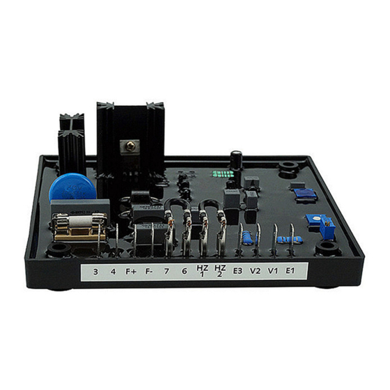
AVC63-4A Outline Diagram (Top View)
AVC63-4A Outline Diagram (Side View)
Rev
-
FOR
NOTE
Power Systems Group
Fax 618 6542351
http://www.basler.com
info@basler.com
V/HZ "CORNER FREQUENCY" SELECTION
AND ADJUSTMENT
For 60 Hz systems, the regulator is preset at
the factory for a 55 Hz "corner frequency."
For 50 Hz systems, a 45 Hz "corner
frequency" is achieved by connecting a
jumper across terminals HZ1 and HZ2.
The corner frequency can be adjusted by the
UF ADJ rheostat on the AVR. Clockwise
rotation results
in
raising
frequency (shifting the curve to the right). To
set the UF rheostat:
1. Adjust the UF Rheostat fully CCW.
2. Start the generator and set at rated
voltage.
3. Adjust the
generator frequency to the
desired kneepoint frequency.
4. Slowly
adjust
the
UF
clockwise (CW) until the generator voltage
just begins to decrease.
Frequency Compensation Curves
OVEREXCITATION SHUTDOWN
Overexcitation shutdown is included that re-
moves the output power if the exciter field
volt-age exceeds 95 Vdc. If exciter field
voltage exceeds 95 Vdc ±5%, the regulator
automatically removes field current, after a
time delay. The time delay is inversely
proportional to the magnitude of the detected
overvoltage condition. At 134 Vdc, the field
voltage is removed after approximately 10
seconds. Refer to the following figure.
Typical Time Delay Characteristic Curves
First Printing
09/01
Revised
the
corner
ADJ
rheostat
Copyright
2001
Advertisement

Subscribe to Our Youtube Channel
Summary of Contents for Power Systems AVC63-4A
- Page 1 FUSES frequency" is achieved by connecting a jumper across terminals HZ1 and HZ2. ELECTRICAL SPECIFICATIONS Although the AVC63-4A has an internal fuse, Dc Output Power: it is recommended that fuses with high The corner frequency can be adjusted by the...
- Page 2 After output power is removed, the regulator b) If a 55 Hz "corner frequency" for 60 RESULT: Voltage regulation should be better can be reset by decreasing the input voltage Hz systems is desired, ensure that the than ±1.0% no-load to full-load. If regulation is to less than 6 Vac for a minimum of 2 HZ1 and HZ2 terminals are open.
- Page 3 Interconnection Diagram, 120/240 V Nominal, 1-Phase, 3-Wire Operational Test...
Need help?
Do you have a question about the AVC63-4A and is the answer not in the manual?
Questions and answers