Advertisement
Table of Contents
- 1 Table of Contents
- 2 Introduction to the R-Series#1
- 3 Installation Terminals and Controls#4
- 4 Installing Annunciators and Expanders#6
- 5 Wiring Diagrams#8
- 6 Troubleshooting#10
- 7 Specifications#11
- 8 Operating the LCD Models#12
- 9 Operating the LED Models#15
- 10 Reading LCD Displays#18
- 11 System Normal Screen#18
- 12 Event Message Screen#18
- 13 Details Screen#19
- 14 Entering a Password#20
- 15 Message Priorities#21
- Download this manual
Advertisement
Table of Contents

Summary of Contents for Edwards R Series
- Page 1 R-Series Remote Annunciators and Expanders Installation and Operation Guide P/N 3100969-EN • REV 05 • ISS 06MAY13...
- Page 2 Other trade names used in this document may be trademarks or registered trademarks of the manufacturers or vendors of the respective products. Manufacturer Edwards, A Division of UTC Fire & Security Americas Corporation, Inc. 8985 Town Center Parkway, Bradenton, FL 34202, USA Version This document applies to R-Series Remote Annunciators and Expanders version 2.0x.
-
Page 3: Table Of Contents
Content Introduction to the R-Series#1 Installation terminals and controls#4 Installing annunciators and expanders#6 Wiring diagrams#8 Troubleshooting#10 Specifications#11 Operating the LCD models#12 Operating the LED models#15 Reading LCD displays#18 System Normal screen#18 ... - Page 4 R-Series Remote Annunciators and Expanders Installation and Operation Guide...
-
Page 5: Introduction To The R-Series#1
Introduction to the R-Series The R-Series Remote Annunciators and Expanders provide remote annunciation for fire and emergency alarm systems. The annunciators offer LCD or LED annunciation, and can include common controls. The expander uses LEDs. The R-Series includes three annunciator models and one expander model. One or two expanders can be connected to any of the annunciator models. - Page 6 The annunciators communicate with the FACP on the RS-485 data riser. This can be configured for Class A or Class B communication. The annunciators do not provide ground fault isolation. The annunciators are stand-alone units that can be powered by the FACP or by an approved power supply.
- Page 7 Part number Description 27193-16 Electrical box, surface mount, white, single-gang. 7300073 24-inch expander cable assembly, includes cable and hardware. 7120313-01 12-inch expander cable (cable only). 7120313-02 24-inch expander cable (cable only). R-Series Remote Annunciators and Expanders Installation and Operation Guide...
-
Page 8: Installation Terminals And Controls#4
Installation terminals and controls Figure 2: Annunciator rear view showing terminals and controls (1) Mounting slot (2) DIP switch (3) Annunciator bus IN/OUT terminals (4) Power riser IN/OUT terminals (5) Transmit and receive communication LEDs (6) Remote key switch terminals (7) Expander cable terminals Figure 3: Expander rear view showing terminals V (-) - Page 9 Table 3: DIP switch settings Switch Description S1 to S5 Annunciator address. The annunciator address (in binary). The factory setting is for address 2. See Table 4 for examples. Possible values: 1 to 31. Baud rate. OFF = 9600 baud (factory default setting) ON = All other baud rates Annunciator circuit type.
-
Page 10: Installing Annunciators And Expanders#6
Installing annunciators and expanders For correct operation, the annunciator must be configured with a unique address, must have the correct baud rate setting, and must be in communication with the FACP. If you are installing a Remote Annunciator and Remote Expanders into RA-ENC2 or RA-ENC3 enclosures, you must install the expanders first. - Page 11 4. Tilt the expander up and slide the mounting slot onto the top flange of the mounting ring, as shown in Figure 4. 5. Tilt the expander down and push the bottom of the expander over the stud- nut. 6. Secure the bottom of the expander to the mounting ring using the captive screw.
-
Page 12: Wiring Diagrams#8
Wiring diagrams All wiring is supervised and power-limited, unless otherwise noted. For terminal connections, refer to the documents listed on the control panel label. Figure 5: Typical Class B wiring AUX_POWER Power Power Power Alarm Alarm Alarm Supervisory Supervisory Supervisory Ground Fault Ground Fault Ground Fault... - Page 13 Figure 8: Typical annunciator wiring RKEY RLCD(-C) / RLED(-C) EGND Ch1( )_IN LOCK(- ) Ch1( )_IN LOCK(+) Ch1( )_OUT Ch1( )_OUT Ch2( )_IN V( )_OUT Ch2( )_IN V( )_OUT Ch2( )_OUT F_OUT Ch2( )_OUT E_OUT D_OUT 24V( )_IN 24V( )_IN C_OUT 24V( )_OUT B_OUT...
-
Page 14: Troubleshooting#10
Troubleshooting When an R-Series annunciator is operating correctly, the Trouble LED follows the panel’s Trouble LED. Annunciators with LCD displays show the same trouble messages as the panel. See the topic “Reading LCD displays” on page 18 for details about message displays. The following table summarizes symptoms and solutions for common installation and operation problems. -
Page 15: Specifications#11
Specifications Voltage 24 VDC, continuous. Do not use control panel AUX power outputs that are interrupted when the panel is reset. Supply must be UL/ULC Listed for use with fire protective signaling systems and have a rating designation of Regulated 24 DC or Regulated 24 FWR. Standby current RLCD, RLCD-R, RLCDF 98 mA... -
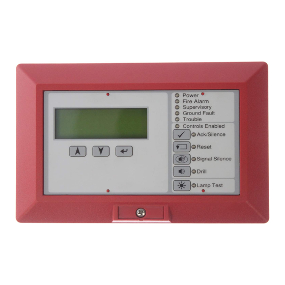
Page 16: Operating The Lcd Models#12
Operating the LCD models Figure 10: Controls and indicators for: RLCD-C, RLCD-CR, RLCD-CF (15) (14) (13) (12) (11) Power Alarm Supervisory Ground Fault Trouble (10) Controls Enabled Ack/Silence Reset Signal Silence Drill Lamp Test Figure 11: Controls and indicators for: RLCD, RLCD-R, RLCDF (15) (14) (13) - Page 17 Table 6: Controls and indicators for the RLCD, RLCD-R, RLCDF, RLCD-C, RLCD-CR, and RLCD-CF Item Description LCD display Displays system status, event messages, and event message details. Up cursor button Scrolls up through the messages in the event message queue. Scrolls up through characters for password entry. Down cursor button Scrolls down through the messages in the event message queue.
- Page 18 Item Description Alarm LED Red LED that indicates an active alarm state (flashing = new alarm event, steady = all current alarm events have been acknowledged). Power LED Green LED that indicates the annunciator is energized. R-Series Remote Annunciators and Expanders Installation and Operation Guide...
-
Page 19: Operating The Led Models#15
Operating the LED models Figure 12: Controls and indicators for: RLED-C, RLED-CR, RLED-CF (15) (14) (13) (12) (11) Power Alarm Supervisory Ground Fault Trouble (10) Controls Enabled Ack/Silence Reset Signal Silence Drill Lamp Test Figure 13: Controls and indicators for the RLED24 and RLED24R R-Series Remote Annunciators and Expanders Installation and Operation Guide... - Page 20 Table 7: Controls and indicators for the RLED-C, RLED-CR, RLED-CF, RLED24, and RLED24R Item Description Zone description label Zone or device description. Active LED Red LED that indicates the zone or device is in the alarm state. Trouble LED Yellow LED that indicates the zone or device is in the trouble state.
- Page 21 Item Description Alarm LED Red LED that indicates an active alarm state (flashing = new alarm event, steady = all current alarm events have been acknowledged). Power LED Green LED that indicates the annunciator is energized. R-Series Remote Annunciators and Expanders Installation and Operation Guide...
-
Page 22: Reading Lcd Displays#18
Reading LCD displays In addition to the system status LEDs, two annunciator models include an LCD display that can show the system status, event messages, or event message details. The display can also be used to enter a password that enables the common control buttons. -
Page 23: Details Screen#19
Details screen Pressing the Enter button while an event message is selected displays the Details screen. The system displays this screen as long as you are pressing the Enter button or using the Up and Down cursor buttons. The system returns to the Event Message screen after approximately 20 seconds of inactivity. -
Page 24: Entering A Password#20
Entering a password When the Controls Enabled LED is off, you need to enter a password to enable the controls. When you press any of the control buttons, the system displays the Enter Password screen. ENTER PASSWORD ?--- SCROLL=+/-NUMBER ENTER =NEXT DIGIT (1) Title line: This is constant text. -
Page 25: Message Priorities#21
Message priorities Event messages are stored in a single list or queue. Within the queue they are sorted into priority according to the event type and the order of event occurrence. The priority of event types is shown in the following lists. US market place 1. - Page 26 R-Series Remote Annunciators and Expanders Installation and Operation Guide...
Need help?
Do you have a question about the R Series and is the answer not in the manual?
Questions and answers