
Related Manuals for Schaltbau CP Series

Summary of Contents for Schaltbau CP Series
- Page 1 Contactors Contactors CP Series 1 pole bi-directional high-voltage contactors, disconnectors, changeover switches for DC and AC Installation and Maintenance Instructions Manual C40-M.en...
-
Page 2: Table Of Contents
3.2 Other dangers .......................... 7 3.3 Measures for avoiding damages and malfunctions ........... 8 Introduction ........................9 4.1 CP series – 1 and 2 pole bi-directional high-voltage contactors, disconnectors, changeover switches for DC and AC ..........9 4.2 Features ............................9 4.3 Applications .......................... - Page 3 10.4 Arc chamber complete .......................40 10.5 Main contacts ........................40 10.6 Contact bridge assembly ....................40 10.7 Magnetic drive complete (without main contacts) ..........40 11. Technical Data ........................41 12. Disposal ...........................41 Contactors CP Series – Installation and Maintenance Instructions 2021-04-12 / V1.1...
-
Page 4: Important Basic Information
- CO = Change Over of risk which, if not avoided, could result in death or serious injury. Since the CP series devices offer a wide range of con- figuration options, not all possible configurations can CAUTION be presented in this manual. -
Page 5: Observing The Instructions
Due to their unique features they can also be used in a variety of applications. The contactors must only be used under operating conditions according to the technical specification and the instructions in this manual. Contactors CP Series – Installation and Maintenance Instructions 2021-04-12 / V1.1... -
Page 6: Ambient Conditions
Make sure that the wire gauge of the earthing cables complies with the specific short circuit conditions. DANGER In the case of a failure of the equipment; don‘t use it anymore immediately contact the manufacturer. Contactors CP Series – Installation and Maintenance Instructions 2021-04-12 / V1.1... -
Page 7: Other Dangers
DANGER All checks and the replacement of components or groups of components may only be carried out by qualified personnel according to the instructions of Schaltbau. All spare parts must be parts de- livered by or released by Schaltbau. Other dangers WARNING Exclusively use the contactors for purposes as indicated in the specications and data sheets. -
Page 8: Measures For Avoiding Damages And Malfunctions
Record the frequency of undoing of the screws in the work log. Replace detent-edged rings or detent-edged washers with new ones after the screws have been undone three times. Contactors CP Series – Installation and Maintenance Instructions 2021-04-12 / V1.1... -
Page 9: Introduction
NO/NC contactors with arc chamber) Modular and compact switchgear for modern power Applications converters With the CP series Schaltbau is introducing once more Main contactor, optional with pre-charging an innovative concept to the switchgear market. The contactor and high-voltage discharging contact for:... -
Page 10: Description
However, if the illustrations on the following pages do not correspond exactly to the present device, the de- scriptions and illustrations are equally valid for the oth- er device models (600 A, 1,200 A, 2,000 A ). Contactors CP Series – Installation and Maintenance Instructions 2021-04-12 / V1.1... -
Page 11: Modular Configuration Options
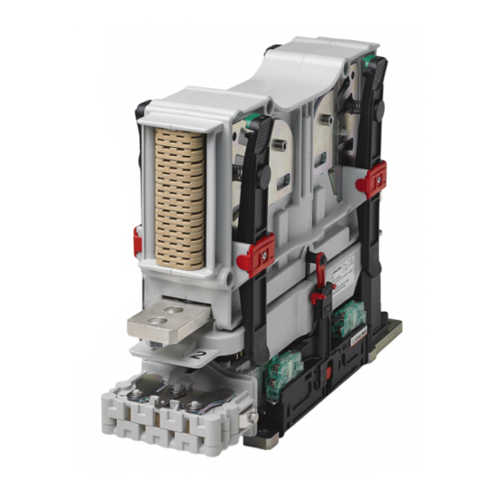
Description Modular configuration options Fig. 1: CP series: Example of modular configuration options for 1,200 A and 2,000 A devices Main Contactor/Disconnector High-voltage discharging contact (CPD) Pre-charging contactor (CPP) to be mounted on the base Auxiliary switch assembly 2x S826... -
Page 12: Configuration Examples
Description Configuration examples Fig. 3: CP series: Configuration example of NO and NC devices with high breaking capacity (large arc chamber) Upper arc chamber area Base plate Lateral arc chamber areas Economy circuit for coil Locking brackets 4x (to lock/unlock the complete arc... - Page 13 Description Fig. 5: CP series: Configuration example of NO and NC devices with load-free breaking capacity (no arc chamber) Main contact terminals 10 Cover (Inspection of main contacts is not required for Earth connection devices with load-free breaking capacity. The cover must Coil terminal (Wago 235) therefore not be removed.)
-
Page 14: Storage
Do not carry the contactor by holding it at the upper part. With the help of a second person, place the con- tactor in an upright position on a stable work- bench or table. Contactors CP Series – Installation and Maintenance Instructions 2021-04-12 / V1.1... -
Page 15: Installation
The mounting screws must be tightened to the specified torque, which depends on the strength class (min. 8.8) of the screws/nuts used. Fig. 8: Examples of permissible mounting positions - CO devices Contactors CP Series – Installation and Maintenance Instructions 2021-04-12 / V1.1... -
Page 16: Required Minimum Clearance
When carrying the contactor al- ways hold it on the base plate. [mm] ±0.1 Fig. 9: Dimensions and arrangement of the mounting holes for devices with 600 A (not to scale) Contactors CP Series – Installation and Maintenance Instructions 2021-04-12 / V1.1... -
Page 17: Tools Required
NC device with medium arc chamber) (on both sides) and nuts. Tightened the mounting screws to the specified torque, which depends on the strength class (min. 8.8) of the screws/nuts used. Contactors CP Series – Installation and Maintenance Instructions 2021-04-12 / V1.1... -
Page 18: Installation Of The Optional Pre-Charging Contactor (Cpp)
(the figure shows a CO device without arc chamber) 4 Nm Fig. 15: 1,200 A and 2,000 A devices: Example for the installa- tion of the CPP at the base plate of the main contactor Contactors CP Series – Installation and Maintenance Instructions 2021-04-12 / V1.1... -
Page 19: Installation Of The Cpp With 600 A Devices
Fig. 17: 600 A devices: Example for the installation of the CPP at a separate mounting position next to the main contactor [mm] ±0.1 Fig. 16: Dimensions and arrangement of the mounting holes for the CPP (not to scale) Contactors CP Series – Installation and Maintenance Instructions 2021-04-12 / V1.1... -
Page 20: Electrical Installation
(for M12 terminal screws). - Schaltbau recommends using Schnorr washers (or similar). The main terminal screws must be tightened to a torque of max. 30 Nm. Contactors CP Series – Installation and Maintenance Instructions 2021-04-12 / V1.1... -
Page 21: Safety
- Socket spanner set hexagon nuts - Open-ended spanner set - Hex key set - Set of POZIDRIV® cruciform screwdrivers - Set of flat bladed screwdrivers - Small cable ties Contactors CP Series – Installation and Maintenance Instructions 2021-04-12 / V1.1... -
Page 22: Connecting The Auxiliary Switches
If applicable bundle and secure the wires using ca- ble ties. 0.7 - 0.9 Nm 0.7 - 0.9 Nm Fig. 18: Example for the connection of auxiliary switches S870 Contactors CP Series – Installation and Maintenance Instructions 2021-04-12 / V1.1... -
Page 23: Connecting The Coil Terminals
Check the routing of the wiring. Wires must not be squeezed or bent. If applicable bundle and secure the wires using ca- ble ties. Fig. 20: Example for the connection of the coil terminals Contactors CP Series – Installation and Maintenance Instructions 2021-04-12 / V1.1... -
Page 24: Connecting The Main Contacts
- Schaltbau recommends using Schnorr washers (or similar). Tighten the terminal screws (3) to a torque of 24 - 30 Nm. Reinstall the arc chamber if applicable, see chapter “9.3.1 Replacing the complete arc chamber unit”. Contactors CP Series – Installation and Maintenance Instructions 2021-04-12 / V1.1... -
Page 25: Connecting The Earth Terminal
(2) on each side 24 - 30 Nm 24 - 30 Nm Fig. 24: Example for the connection of the main circuit with two cables (2) on each side Contactors CP Series – Installation and Maintenance Instructions 2021-04-12 / V1.1... -
Page 26: Connecting The Optional Pre-Charging Contactor (Cpp)
Fig. 28: Connecting the optional high-voltage discharging contact (CPD) Fig. 26: With 1,200 A and 2,000 A devices: Connecting the op- tional pre-charging contactor (CPP) mounted on the base plate of the main contactor Contactors CP Series – Installation and Maintenance Instructions 2021-04-12 / V1.1... -
Page 27: Checks
- If applicable bundle and secure wires using ca- ble ties. After every installation or after maintenance, check the contactor for correct operation in accordance with the following standards: - EN/IEC 60077-2 - EN/IEC 60947-4-1 Contactors CP Series – Installation and Maintenance Instructions 2021-04-12 / V1.1... -
Page 28: Maintenance
Immediately replace all damaged only required for devices with arc cham- components with new compo- ber, not permissable for devices without nents. arc chamber) Inspection of the auxiliary switches Every 2 years Contactors CP Series – Installation and Maintenance Instructions 2021-04-12 / V1.1... -
Page 29: Regular Check Activities
Contactor/base plate Check for: In case of faults: mounting loose or missing fastening elements tighten loose fastening elements and replace missing fastening elements im- mediately fix a loose contactor Contactors CP Series – Installation and Maintenance Instructions 2021-04-12 / V1.1... - Page 30 The fixed drive unit due to operation with impermissi- contacts and the contact bridge from the ble, too high coil voltage defective device can still be used Contactors CP Series – Installation and Maintenance Instructions 2021-04-12 / V1.1...
-
Page 31: Corrective Maintenance
(3) at the bottom. Remove the complete arc chamber unit (2) up- wards from the magnetic drive unit (4). Fig. 30: Remove and install the arc chamber unit (medium arc chamber) Contactors CP Series – Installation and Maintenance Instructions 2021-04-12 / V1.1... -
Page 32: Checking The Main Contacts
Before beginning any work on the contac- tors, make sure that there is no voltage present, all safety regulations are fully ob- served. Refer also to section „Dangers and security measures“ on page 6. Contactors CP Series – Installation and Maintenance Instructions 2021-04-12 / V1.1... -
Page 33: Replacing The Contact Bridge
(1), spring (2), spring support (3) and contact Fig. 33: NO/NC contactors with cover only – remove and in- bridge (4). Use only the new parts 1 to 4. stall the contact bridge Contactors CP Series – Installation and Maintenance Instructions 2021-04-12 / V1.1... -
Page 34: Replacing The Fixed Contacts
- Set of torx bits - Socket wrench set - Open-end wrench set - Torque wrench Fig. 36: 600 A NO/NC contactors with arc chambers – remove the fixed contacts Contactors CP Series – Installation and Maintenance Instructions 2021-04-12 / V1.1... - Page 35 1,200 A 1,200 A 12 Nm 12 Nm 2,000 A 2,000 A Fig. 37: 1,200 A and 2,000 A NO/NC contactors with arc cham- bers – install the fixed contacts Contactors CP Series – Installation and Maintenance Instructions 2021-04-12 / V1.1...
-
Page 36: Replacing The Auxiliary Switch Assembly
Unscrew the 2 fixing screws (5). Install the shaft circlip (1) in the groove on the Pull the actuating arm from shaft (7) and remove shaft (7). the auxiliary switch assembly (6). Contactors CP Series – Installation and Maintenance Instructions 2021-04-12 / V1.1... -
Page 37: Replacing The Optional Pre-Charging Contactor (Cpp)
Fig. 42: With 600 A devices: Replace the pre-charging disconnected, see “8.4.8 Connecting the optional contactor (CPP) mounted at a separate mounting po- sition next to the main contactor pre-charging contactor (CPP)”. Contactors CP Series – Installation and Maintenance Instructions 2021-04-12 / V1.1... -
Page 38: Replacing The Optional High-Voltage Discharging Contact (Cpd)
Refer also to section „Dangers and security measures“ on page 6. Spare parts required High-voltage discharging contact (CPD), see chapter “10. Spare parts” Contactors CP Series – Installation and Maintenance Instructions 2021-04-12 / V1.1... -
Page 39: Checks
(CPD) ble ties. After every installation or after maintenance, check the contactor for correct operation in accordance with the following standards: - EN/IEC 60077-2 - EN/IEC 60947-4-1 Contactors CP Series – Installation and Maintenance Instructions 2021-04-12 / V1.1... -
Page 40: Spare Parts
M = monostable (on via supply voltage) Size 2+3: 1,200/2,000 A - 10MW N = monostable (on via separate control input) Size 1: 600A-2MW B = bi-stable Size 2+3: 1,200/2,000 A - 5MW Contactors CP Series – Installation and Maintenance Instructions 2021-04-12 / V1.1... -
Page 41: Technical Data
Technical Data 11. Technical Data Technical data and information for the contactors of the CP series contactors are given in our C40 catalogue. Schaltbau products are subject to continual improve- ment. Therefore, the product information in catalogues, data sheets, etc. may change at any time. Therefore, only the latest version of a catalogue is valid at any time –... - Page 42 Notes Notes Contactors CP-Series – Installation and Maintenance Instructions 2021-04-12 / V1.1...
- Page 43 Notes Contactors CP-Series – Installation and Maintenance Instructions 2021-04-12 / V1.1...
- Page 44 High-voltage heaters ■ High-voltage roof equipment ■ Equipment for electric brakes ■ Design and engineering of train electrics to customer requirements We reserve the right to make technical alterations without prior notice. Printed in Germany For updated product information visit www.schaltbau-gmbh.com..
Need help?
Do you have a question about the CP Series and is the answer not in the manual?
Questions and answers