Table of Contents
Advertisement
Quick Links
Advertisement
Table of Contents

Subscribe to Our Youtube Channel
Related Manuals for Roth ROTILABO CR-DS 40

Summary of Contents for Roth ROTILABO CR-DS 40
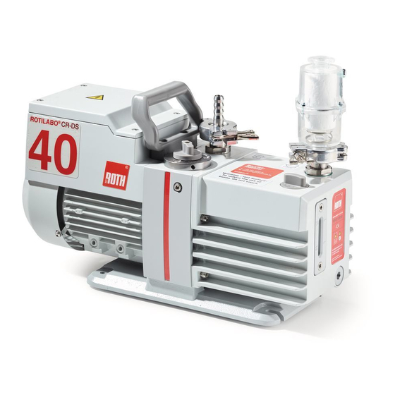
- Page 1 Operation Manual ROTILABO CR-DS 40 ® Rotary vane pump Two-stage...
- Page 2 Reprinting or reproduction of this manual, including extracts, is not allowed without the prior written permission of Carl Roth GmbH + Co. KG. All rights under the copyright laws are expressly reserved by Carl Roth GmbH + Co. KG. We reserve the right to make changes and amendments.
-
Page 3: Table Of Contents
CONTENTS IMPORTANT INFORMATION Pump Location / Environmental Conditions ......19 .........4 General References ............19 Meaning of the Warning and Information note .....4 Installation and Connection ..........20 General Information ..............4 5.5.1 Connecting to the Electricity Supply ........21 Target Groups ...............5 5.5.2 Change the Voltage Setting ..........21 Intended Use .................5 5.5.3 Motor Protection ..............22 Use for an Unauthorized Purpose ........5... -
Page 4: Important Information
IMPORTANT INFORMATION 1.1 Meaning of the Warning and Information notes Take note of the warning notes which are in the following boxes: CAUTION ! / WARNING ! Hazard which may lead to serious injuries or material damage. WARNING ! Hot surface which may lead to serious injuries or material damage. Information which are only relevant of CE operation are marked in following boxes: ONLY RELEVANT FOR CE (220-240V / 50HZ ) OPERATION 1.2 General Information... -
Page 5: Target Groups
IMPORTANT INFORMATION 1.3 Target Groups This operating manual is intended for the personnel planning, operating and maintaining standard, two-stage, Rotary vane pumps. This group of people includes: • Designers and fitters of vacuum apparatus • Employees working on commercial laboratory and industrial vacuum technology applications •... -
Page 6: Basic Safety Instructions
BASIC SAFETY INSTRUCTIONS 2.1 General Information IMPORTANT SAFETY INSTRUCTIONS – SAVE THESE INSTRUCTIONS To reduce the risks of fire or explosion, electrical shock, and the injury to persons, read and understand all instructions included in this manual. CAUTION ! Be familiar with the controls and the proper usage of the equipment •... -
Page 7: Hazardous Substances
BASIC SAFETY INSTRUCTIONS 2.4 Hazardous Substances The operating company bears the responsibility for the use of the rotary vane pump. CAUTION ! Hazardous substances in the gases to be pumped can cause personal injuries and property damage. Pay attention to the warning notices for handling hazardous substances. The local regulations apply in foreign countries. -
Page 8: Description
DESCRIPTION 3.1 Design The ROTILABO CR-DS 40 vacuum pumps are oil-sealed, two-stage Rotary vane pumps. ® The drive motor is directly flange-mounted onto the motor cover of the pump holder and the pump shaft and the motor shaft are connected to each other by an elastic coupling. The bearings of the interior pump body are force-fed lubricated sliding bearings. -
Page 9: Scope Of Delivery
DESCRIPTION 3.3 Scope of Delivery Followed the scope of delivery for standard model numbers. EMEA Description 230 V, Standard Ordering Information ROTILABO CR-DS 40: 1A9E.1 ® Factory wired for 220-240 V/50 Hz, 230 V/60 Hz Voltage switchable Centering ring with dirt trap (DN 16 KF) Centering ring (DN 16 KF) Clamping ring (DN 16 KF) Oil mist filter OME10/16... -
Page 10: Working Principle Of Rotary Vane Pumps
DESCRIPTION 3.4 Function 3.4.2 Working Principle of Rotary vane pumps Pressure reduction in a closed system is accomplished by repeatedly removing a portion of the original volume of gas contained in the system. Removal is performed by the action of the rotating elements of the pump which cause a given space to be successfully enlarged and diminished. -
Page 11: Working Principle Of Two-Stage Rotary Vane Pumps
DESCRIPTION 3.4 Function 3.4.3 Working Principle of Two-Stage Rotary vane pumps (ROTILABO CR-DS 40) ® Two pump stages (fore-stage and high-stage) are arranged in series in order to improve the end pressure and the pumping speed at lower pressures. The intake takes place in the first stage (high-stage), the compression and the outlet in the second stage (fore-stage). - Page 12 DESCRIPTION 3.4 Function 3.4.3 Working Principle of Two-Stage Rotary vane pumps (ROTILABO CR-DS 40) ® Effects of Continued Pressure Reduction The quantity of gas in the vessel (6) is reduced with each evacuation cycle. The gas remaining in the vessel expands to fill the vessel and consequently with each cycle the pressure in the vessel is reduced. This is a manifestation of Boyle’s Law which states that, for a constant temperature, the volume of a body of gas is inversely proportional to its pressure;...
-
Page 13: Oil Functions
DESCRIPTION 3.4 Function 3.4.4 Oil Functions Vacuum pump is shipped without oil inside to prevent possible spillage during shipment. Oil must be added prior to use! WARNING ! The oil fulfils the following functions in the vacuum pump: • Lubricating the sliding parts, such as rotor, vane, radial shaft seals •... -
Page 14: Gas Ballast
DESCRIPTION 3.4 Funktion 3.4.7 Gas Ballast Condensates could have collected in the vacuum pump if: • The vacuum pump is new • It has not been used for long periods • The pump's maximum tolerance of water vapour pressure has been exceeded When pumping condensable vapours, they may be compressed during the compression phase above the saturated vapour pressure and condense. -
Page 15: Technical Data
TECHNICAL DATA 4.1 Dimensions Fig. 4 Dimensions (in mm) 384 mm 183 mm 30 mm 135,5 mm 184 mm 210,5 mm 90 mm 138 mm 224 mm 4.2 Pumping Speed / Intake Pressure – Diagram without gas ballst Intake pressure (mbar) with gas ballst Fig. -
Page 16: Device Data
TECHNICAL DATA 4.3 Device Data Parameter Unit ROTILABO CR-DS 40 ® Free Air Displacement (max. pumping speed) - @ 50Hz /h (l/min) 2.5 (41.7) - @ 60Hz CFM (l/min) 1.8 (50) Pumping speed (Ø-data 133 to 1013 mbar) - @ 50Hz m³/h (l/min) 2.3 (38.3) - @ 60Hz... -
Page 17: Lubrication Data
TECHNICAL DATA 4.5 Lubrication Data Welch Directorr™ Premium vacuum oil is a triple-distilled hydrocarbon oil using severely hydro treated base stock. The oil is designed to resist breakdown at higher RPMs and operating temperatures of direct-drive vacuum pumps. The hydro treating virtually eliminates aromatics and sulfur to give good resistance to sludge and varnish formation over time in corrosive environments. -
Page 18: Installation And Operation
INSTALLATION AND OPERATION 5.1 Unpacking Carefully unpack the rotary vane pump. Keep all paperwork and inspection tags for future reference. Check the pump for: • Transport damage • Conformity with the specifications of the supply contract (model, electrical supply data) •... -
Page 19: Pump Location / Environmental Conditions
INSTALLATION AND OPERATION 5.3 Pump Location / Environmental Conditions The pump should be located in a clean and well-ventilated area and adequate space should be provided wherever possible for routine maintenance such as oil changes. For best performance, the pump should be located as closely as possible to its system. Determining factors for pump location should include length and size of connections, the number of bends, and the type of exhaust connections. -
Page 20: Installation And Connection
INSTALLATION AND OPERATION 5.5 Installation and Connection 1. Set the rotary vane pump on a flat and horizontal surface. If more rigid mounting is required, bolt the pump base to the surface. See chapter 5.2 Pump Mounting 2. Remove the clamping ring and the protection cap of the suction and exhaust ports 3. -
Page 21: Connecting To The Electricity Supply
INSTALLATION AND OPERATION 5.5 Installation and Connection 5.5.1 Connecting to the Electricity Supply The standard pump is supplied with complete electrical wiring. It is connected via an appliance cable and a power supply plug. If the supply cord is damaged, it must be replaced by the manufacturer, its service agent or similarly qualified persons in order to avoid a hazard. -
Page 22: Motor Protection
INSTALLATION AND OPERATION 5.5 Installation and Connection 5.5.3 Motor Protection All A.C. motors are provided with a thermal overload protection ex works, protecting the motor and vacuum pump from damage or destruction, respectively. The motor manufacturer makes motor thermal overload protection available as an aid to minimize motor failure. -
Page 23: Operating Temperature
INSTALLATION AND OPERATION 5.7 Operating Temperature The function of the vacuum pump filled with Directorr™ Premium vacuum oil is guaranteed between ambient temperatures of 10°C and 40°C. The lowest starting temperature is 12°C. Thepump must be vented on the suction-side (suction port open). In dependence on the operation mode, the casing temperature can reach 90°C. -
Page 24: Gas Ballast Control
INSTALLATION AND OPERATION 5.9 Gas Ballast Control The principle of the gas ballast is described in chapter 3.4.7 Gas Ballast. To open or close the gas ballast turn the gas ballast switch to the position open or close. Operation with gas ballast when drawing off condensable vapours We suggest operation with the gas ballast valve open, provided that the composition of gas in the vacuum pump to be drawn off is not known and cannot be ruled out. -
Page 25: Side Panel Fitting Port
INSTALLATION AND OPERATION 5.11 Side Panel Fitting Port Some applications call for a gas purge using a clean dry gas such as nitrogen. An external gas supply can be routed into the gas ballast assembly using that port. Disasemble the Office S3258-99 Install the Fitting to the port S3257-99 Install the gasket... -
Page 26: Closing Down
INSTALLATION AND OPERATION 5.12 Closing down A few simple precautions are necessary before performing a pump shutdown. 1. If a pressure gauge is connected to the system, first isolate the pressure gauge, then turn off the power to the pump and open the system to the atmosphere. 2. -
Page 27: Maintenance And Servicing
MAINTENANCE AND SERVICING Under normal operating conditions the maintenance of the rotary vane pump is limited to: • External cleaning • Checking running noises • Checking the level and quality of the oil • Regular oil changes These maintenance intervals must be specified according to the prevailing operating conditions and adhered to. -
Page 28: Oil Level Control
MAINTENANCE AND SERVICING 6.1 Oil Level Control Check the oil level regularly! CAUTION ! The oil consumption varies according to the vacuum pump’s operating conditions. In order to keep the vacuum pump at all times in an optimum operating condition, the oil level must be inspected at the oil sight glass. -
Page 29: Oil Change
MAINTENANCE AND SERVICING 6.3 Oil Change If the vacuum pump has been used to pump media which are dangerous to health then all measures must be taken to protect the service and operating personnel! WARNING ! 6.3.1 Draining the Oil 1. -
Page 30: Flushing
MAINTENANCE AND SERVICING 6.3 Oil Change 6.3.3 Flushing If the oil is heavily contaminated, the vacuum pump must be flushed, e.g.: • Heavy clouding by condensates • Suspended particles such as dust, fibres, abraded particles • Dark coloration of the oil The flushing liquid should be the type of oil which is currently being used. -
Page 31: Troubleshooting
TROUBLESHOOTING Only manufacturing firm and authorized service workshops may work on the pump and their accessories during the warranty period. Trouble Cause Remedy by Remedy with Qualified No power supply Check electrical installation electrician Motor defective Exchange Service workshop Coupling defective Repair and/or exchange Vacuum pump does not start... - Page 32 TROUBLESHOOTING 6.5 Major Factory Repair Trouble Cause Remedy by Remedy with Check that the oil circulation is functioning, measure the oil pressure at operating tempe- Vacuum pump oil supply interrupted User or rature, 1 – 1.2 bar overpres- Service sure, check that the pipes are workshop clear and have no leaks Oil with too low viscosity used...
-
Page 33: Overview Of Accessories
OVERVIEW OF ACCESSORIES 8.1 Overview and Order Numbers Type Product name Description Art. Nr. Oil Mist Separator AKD 16 320015 Exhaust Filter DN 16 KF Replacement element for OME 10/16, AKD 16 800160 Cold Trap KFG16 set: Trap Cold trap with cold finger, 500 mm metal hose, DN 16 KF 330055 centering ring and clamping ring... -
Page 34: Overview Of Spare Parts
OVERVIEW OF SPARE PARTS The overview of spare parts contain all service kits, single spare parts with all the information necessary for ordering. When ordering please quote the order number, description and quantity! We are not liable for any damage caused by the installation of any parts not supplied by the manufacturer. -
Page 35: List Of Spare Parts
OVERVIEW OF SPARE PARTS 9.2 List of Spare Parts 46 45 55 54 97 96 Service Kit Seal Kit Fig. 12 Exploded view ROTILABO CR-DS 40 ®... - Page 36 OVERVIEW OF SPARE PARTS Item no. Description Qty. Motor Handle Coupling Flat key Set screw Coupling Element Trestle Red strip Right side overlay Felt Base Foot pad O-ring O-ring O-ring Left side overlay PTFE flat washer Short gas ballast mouth O-ring Inlet/Out Port O-ring...
- Page 37 OVERVIEW OF SPARE PARTS Item no. Description Qty. O-ring Busing Oil Seal Fore pump stator O-ring Gas ballast valve head Spring O-ring Fore rotor Vane spring Vane Coupling Back pump stator Stop plunger Exhaust valve seat Oil baffle cover Flat washer Spring Exhaust vane Back rotor...
-
Page 38: Warranty
WARRANTY This Welch product is warranted to be free from defects in material and workmanship. The liability of Gardner Denver Thomas, Inc. under this warranty is limited to servicing, adjusting, repairing or replacing any unit or component part which in the judgment of Gardner Denver Thomas, Inc. has not been misused, abused or altered in any way causing impaired performance or rendering it inoperative. -
Page 39: Ec Declaration
Wuxi New District, Jiangsu PC 214142 China Appliance description: Rotary Vane pump Document-No.: CRVpro2-Carl Roth Series: Rotilabo® CR-DS 40 Model NO. 1A9E.1 EC-declaration of conformity according to Machinery Directive We hereby declare, that the appliance described above, based on it’s concept and design as well as the models... - Page 40 Global Contact: Carl Roth GmbH + Co. KG · Schoemperlenstr. 3-5 · 76185 Karlsruhe Post office box 10 01 21 · Germany Phone: +49 (0)721/5606-0 · Fax: +49 (0)721/5606-149 info@carlroth.de · www.carlroth.de...
Need help?
Do you have a question about the ROTILABO CR-DS 40 and is the answer not in the manual?
Questions and answers