Table of Contents
Advertisement
Quick Links
IF USING INTUMESCENT KIT R97-XX, REFER TO INSTRUCTIONS
WITH KIT AS INSTALLATION DEPTHS WILL INCREASE
IMPORTANT NOTICE - FOR FIRE DOOR INSTALLATIONS
REFER TO ITEM 1 IN FITTING INSTRUCTIONS
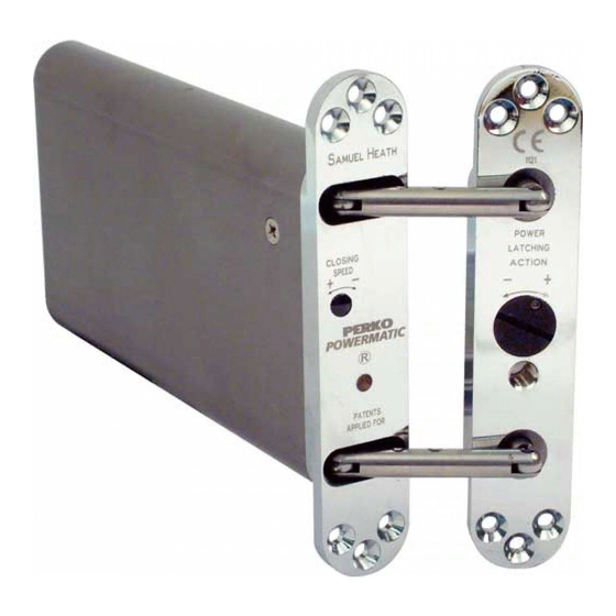
• UKCA marked
• CE marked and adjustable to conform to power size 3 of Controlled Door Closing
Device. BS EN1154: 1997 (Test door 60kg/132lbs).
• 1 Hour Fire Test BS EN1634-1: 2000.
• Adjustable speed control.
• Adjustable power latching action.
• 1 1/2 Pairs of hinges should be used in conjunction with this closer on all doors.
• Suitable for doors opening to a maximum of 105°. A door stop should be fitted.
• Maximum door weight 80kg/175lbs, width 950mm/38".
• Suitable for latched and unlatched doors.
• Should NOT be used with rising butt hinges.
• For use with concealed hinges contact our Customer Service Team - details on
the back of this leaflet.
PLEASE READ FITTING INSTRUCTIONS THOROUGHLY
BEFORE INSTALLATION
Advertisement
Table of Contents

Subscribe to Our Youtube Channel
Summary of Contents for Powermatic R100
- Page 1 IF USING INTUMESCENT KIT R97-XX, REFER TO INSTRUCTIONS WITH KIT AS INSTALLATION DEPTHS WILL INCREASE IMPORTANT NOTICE - FOR FIRE DOOR INSTALLATIONS REFER TO ITEM 1 IN FITTING INSTRUCTIONS • UKCA marked • CE marked and adjustable to conform to power size 3 of Controlled Door Closing Device.
- Page 2 A DBB morticer, a long shaft and WB27 and • Power Drill WB29 cutters will be required • Tape Measure Eye Protectors, Ear Defenders • Pencil and a Face Mask are • Adjustable Spanner recommended during installation ® of Powermatic • Ruler...
- Page 3 IMPORTANT NOTICE Fig. 1 DOOR CLOSERS FITTED TO A FIRE DOOR ® • Powermatic , conforms to Power Size 3 of Controlled Door Closing Device Standard BS EN1145:1997 when the power latching action is set to maximum. • Turn adjuster screw fully to positive (+) as explained in 9.
- Page 4 To achieve a maximum opening angle of 105° the centre of the closer must be no more than 35mm / 1 3/8” from the pivot point of the hinge. Fig. 2 IMPORTANT To ensure the 35mm / 1 3/8” distance is not exceeded the closer and fixing plate can both be offset in the door leaf and jamb (closer to the hinge pivot point) by up to a maximum of 6mm / 1/4”...
- Page 5 FRAME PREPARATION FOR DOOR PREPARATION FOR FRAME PLATE BODY & DOOR PLATE • Drill 4 x 26mm / 1 1/16” NB To ensure correct operation of Ø x 185mm / closer there must be a 3mm / 1/8” gap 7 5/16” deep holes to accept closer body as between the two fixing plates when indicated on template.
- Page 6 INSTALLING CLOSER • Insert closer body into door. • Insert the Allen keys (C) through both top and bottom link rod holes. • Insert extractor bolt (E) into position and Both Allen keys must be correctly rotate clockwise until holes in link rods located appear.
- Page 7 ADJUSTMENT - CLOSING SPEED • With the closer secure and now held • Remove dust cap. open by Allen keys, if necessary firmly push both link rods across door plate • Use one of the Allen keys (C) to and offer frame plate into frame void. adjust closing speed.
- Page 8 ADJUSTMENT - The Powermatic is protected by the following Patents and Applications. POWER LATCHING ACTION CANADA 2365822 2436363 HONG KONG 1038953 JAPAN 2000-602490 SINGAPORE 82862 TAIWAN 156554 6625847 2004/0111831 GB25447175 GB2415014 EP1605126 AUSTRIA BELGIUM DENMARK FRANCE GERMANY IRELAND EP1605126 ITALY...
Need help?
Do you have a question about the R100 and is the answer not in the manual?
Questions and answers