Table of Contents
Advertisement
Quick Links
Advertisement
Table of Contents

Summary of Contents for Pewatron FCX-ML-CH Series
- Page 1 103-12-306-003-EH-0412.pdf Manual Oxygen module FCX-MLxx-CH...
- Page 2 This document may be used by the receiver for its designated purposes. It mustn’t be copied or translated in any way without special consent in advance. Technical amendments reserved. Copyright: Pewatron AG Sold in North America by: PEWATRON AG Servoflo Corporation...
-
Page 3: Table Of Contents
103-12-306-003-EH-0412.pdf 1 List of Contents Page ....................................List of Contents ................................... Customer Service ................................... Security Information ..................................Measuring Principle ....................................Operation Start ................................Mechanical Installation ................................Pneumatic Connections ................................Electrical Connections ........................................5.3.1 Supply ....................................5.3.2 Analog Output ................................Environment Conditions .................................... -
Page 4: Customer Service
103-12-306-003-EH-0412.pdf 2 Customer Service We at PEWATRON AG would like to offer the best possible customer service. Should you have any questions, problems or comments regarding your FCX-MLxx-CH, we would appreciate if you get in touch with us. We recommend that all services, including repairs of the device, will only be taken care of by either our customer service or by specially trained staff. -
Page 5: Security Information
103-12-306-003-EH-0412.pdf 3 Security Information Safety hazards that can endanger humans or do damage to the devices are specially mentioned in the user manual. Before installing the device you should read the instructions carefully. Please take note of all paragraphs that point out possible hazards. Warnings and instructions are expressed as followed: Means that ignoring this instruction can endanger humans Warning... -
Page 6: Measuring Principle
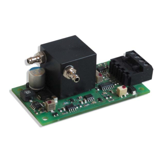
103-12-306-003-EH-0412.pdf 4 Measuring Principle The sensor module is a complete solution for measuring oxygen within the range of 0,1...25%. The sensor and the electronics are united on one board. The electronic amplifies the sensor signal and puts it out as logarithmic current output signal 4…20mA ( according IEC 60381 ) Principle sketch of the O Limiting-current sensor The zirconia is pervious to oxygen ions when heated up to approx. -
Page 7: Operation Start
103-12-306-003-EH-0412.pdf 5 Operation Start 5.1 Mechanical Installation The dimensions of the board are 75 x 40 x 28mm. On every corner are mounting wholes with a diameter of 3,5 mm. The board holds highly sensitive switches. While installing make sure that no components get damaged mechanically Attention 5.2 Pneumatical Connections... -
Page 8: Electrical Connections
103-12-306-003-EH-0412.pdf 5.3 Electrical Connections 5.3.1 Supply The module gets supplied with 7...28VDC through the clamps 1 (+) and 2 (-), approx. 200mA (24VDC). 5.3.2 Analog Output For the output signal the clamps 3 (+) and 4 (-) can be used. 6 Environment Condition Also see item 11 in our specifications, especially for the temperature and humidity range (non- condensing). -
Page 9: Gas Flow
103-12-306-003-EH-0412.pdf 8 Gas Flow Heed the following points: The flow should not be smaller than 0,1 and not larger than 3,0l/min. Optimal 0,5l/min We recommend to use a suitable filter, since the gas flow can contaminate the sensor, which will shorten its life span considerably. Avoid condensation (H O) inside the sensor housing. -
Page 10: Calibration If The Sensor Needs To Replacing
103-12-306-003-EH-0412.pdf Attach the module to the supply Use the sensor in regular air (20,9% O After 10min. adjust the output signal using the potentiometer 2. In a clean environment the amplifier should have an output signal of 17,44mA (0,05mA). Flow pure N After approx. -
Page 11: Important Advice
103-12-306-003-EH-0412.pdf 10 Important Advice 10.1 Restrictions Don’t separate the sensor from the circuit board. Don’t change the length of the lead wires. Don’t operate this sensor in a high oxygen concentration (>25% O If the sensor is exposed to such high oxygen concentration, limited output over 20mA will be observed. - Page 12 Sold in North America by: Sales Other Countries Servoflo Corporation 75 Allen Street Lexington, MA 02421 PEWATRON AG Tel: 781-862-9572 Thurgauerstrasse 66 www.servoflo.com / info@servoflo.com CH-8052 Zurich Phone + 41 44 877 35 00 + 41 44 877 35 25 info@pewatron.com...
Need help?
Do you have a question about the FCX-ML-CH Series and is the answer not in the manual?
Questions and answers