Table of Contents
Advertisement
Quick Links
NextGen CoolLinks™ HVAC Controller
Installation & Operations Manual
®
This product manual describes the steps to install and operate the Marvair
NextGen CoolLinks™ HVAC controller. The
information contained in this manual is to be used as a guide only. This manual does not supersede or circumvent any
applicable national or local codes.
If you are installing the controller, scan the entire manual before starting work. The HVAC units should be installed before
the NextGen CoolLinks™ controller. For the installation instructions for the Marvair units, please contact Marvair. The
latest versions of all literature including the manuals can be downloaded from the Marvair customer portal on the Airxcel
website at www.airxcel.com.
®
Marvair
, Division of Airxcel™, Inc.
156 Seedling Dr. Cordle, GA. 31015
(229) 273-3636
Email:
marvairtech@airxcel.com
Web site: www.marvair.com
1
NG-IOM-ATT Release 1.2
July 12, 2019
Advertisement
Table of Contents

Summary of Contents for Marvair CoolLinks NextGen
- Page 1 If you are installing the controller, scan the entire manual before starting work. The HVAC units should be installed before the NextGen CoolLinks™ controller. For the installation instructions for the Marvair units, please contact Marvair. The latest versions of all literature including the manuals can be downloaded from the Marvair customer portal on the Airxcel website at www.airxcel.com.
-
Page 2: Table Of Contents
6.6 Generator Running 6.7 Hydrogen Alarm 6.8 RBS HVAC1 Fail Alarm 6.9 RBS HVAC2 Fail Alarm 6.10 RBS Temp High Alarm 6.11 RBS Temp Low Alarm 6.12 Standalone Operation (CoolLinks™ Interface Only) Marvair Contact Information………………………………………………………………………………………37 NG-IOM-ATT Release 1.2 July 12, 2019... - Page 3 IMPORTANT is used to point out helpful suggestions that will result in an improved installation, reliability or operation. Confidentiality: ® This document and the information contained herein are confidential and are the property of Marvair . It may not in any ®...
-
Page 4: Materials Required For Installation
2.1 Equipment Architecture ® Each telecommunications shelter is equipped with an externally mounted Marvair DAC/WAC DC Free-Air unit and up to two wall mount mechanical-only cooling HVAC units connected to the NextGen CoolLinks™ controller. - Page 5 NextGen CoolLinks™ Controller Unit 3 DX Remote HVAC Interface Unit 2 DX HVAC Unit 1 DAC/WAC Smart Phone Interface Exhaust Ethernet Damper Hardwired or Ethernet Optional (Hardwired or Ethernet) Hardwired Figure 1: NextGen CoolLinks™ Architecture NG-IOM-ATT Release 1.2 July 12, 2019...
-
Page 6: Cooling Control
2.2 Cooling Control The DAC/WAC unit provides the primary shelter cooling. The secondary HVAC mechanical-only cooling units operate in the event that internal temperatures exceed a threshold or failure of the DAC/WAC unit. When commanded to run, the DAC/WAC unit fully opens the its internal damper and the remote exhaust damper then regulates the blower speed dependent on internal shelter temperature. -
Page 7: Dac/Wac Standalone Operation
2.4 DAC/WAC Standalone Operation If the control board in the DAC/WAC unit is unable to communicate with CoolLinks™ controller for a period of sixty seconds, the DAC/WAC unit will select standalone mode. Here, the unit will run its blower at 100% and both the DAC/WAC and exhaust dampers will be fully opened. -
Page 8: Mechanical Installation
Chapter 3 Mechanical Installation 3.1 Control Enclosure The NextGen CoolLinks™ enclosure can be mounted directly on the wall in any suitable location on the inside of the shelter; the enclosure does not have to be mounted on the same wall as the DAC/WAC or HVAC units. However, there are some physical constraints that should first be considered prior to mounting: DAC/WAC Unit: one, 50ft. - Page 9 Figure 2: NextGen CoolLinks™ Enclosure Dimensions and Mounting Locations Figure 3: Inside Sensor Mounting Location NG-IOM-ATT Release 1.2 July 12, 2019...
-
Page 10: Electrical Installation
Chapter 4 Electrical Installation WARNING ELECTRICAL SHOCK HAZARD Failure to follow safety warnings exactly could result in serious injury, death, and/or property damage. Turn off electric power at the service panel or fuse box BEFORE making any electrical connections and ensure a proper ground connection is made. 4.1 Electrical Connection Overview Turn each of the four captive screws one quarter-turn, counter-clockwise to remove the front cover from the NextGen CoolLinks™... -
Page 11: Control Power (48 Vdc)
4.2 Control Power (48 VDC) The NextGen CoolLinks™ controller requires a two-conductor, 5A, 48VDC feed from the shelter DC plant. The wire type must be per AT&T policy document ATT-002-290-701, Cell Site DC Power Wiring Requirements . All wire connections in the DC plant must use two-hole compression lugs sized for the wire gauge. -
Page 12: Inside Temperature & Humidity Sensor
4.3 Inside Temperature & Humidity Sensor This sensor provides the main control input for the controller. There are two possible sensors, the Air Test EE10 and Prism Systems Temperature & Humidity sensor. Both sensors provide a temperature range of 32°F - 122°F and a relative humidity range of 0% - 100%. -
Page 13: Dac/Wac Unit
4.4 DAC/WAC Unit The NextGen CoolLinks™ controller contains a five-port Ethernet router as shown below. All Ethernet devices in the system connect through this router. The right-most port connects to the main processor circuit board. The Ethernet cable from the DAC/WAC connects to any open port (the ports on the router are not dedicated) and to the RJ45 plug on the CoolLinks™... -
Page 14: Hvac Units
4.5 HVAC Unit 4.5.1 Hardwired Interface (Default) The hardwired interface provides control for the mechanical cooling and heating functions of the HVAC unit. At a minimum, a five-wire thermostat cable (not supplied) is required for control of the compressor, evaporator blower, and heating element. - Page 15 4.5.2 CoolLinks™ Interface The CoolLinks™ interface provides enhanced control and diagnostics for the mechanical cooling and heating functions of the HVAC unit. The Ethernet cable from the CoolLinks™-equipped HVAC unit connects to any open port on the router and to the RJ45 plug on the CoolLinks™ board as shown below. Figure 10: CoolLinks™...
-
Page 16: Smoke Detector, Hydrogen Detector, Generator Running
DC control power for the CoolLinks™ board in the DX unit can be sourced from the controller from any one of the four 48VDC terminal blocks. Ensure that the slider switch (1) is in the left position (green power LED (3) off). On the two- position terminal block (2) connect +48VDC to the R terminal (5) and RTN to the C terminal (6) on CoolLinks board. - Page 17 Hydrogen Detector: Figure 15: Wiring Connections With or Without Hydrogen Detector Generator Running: Figure 16: Wiring Connections With or Without Generator Running Feedback NG-IOM-ATT Release 1.2 July 12, 2019...
-
Page 18: Rbs Alarms
4.7 RBS Alarms A dedicated 66-block provides all controller hardwired alarms. Normally-open and normally-closed contacts are available for each of the eight possible RBS alarms. For installations with limited interior space, a 25-pair pigtail is provided rather than the dedicated 66-block to allow the alarms to be wired directly to the main shelter alarm block. Figure 17: RBS Alarm Punch Down Block 4.8 Bonding All of the electrical components within the NextGen CoolLinks™... -
Page 19: Operator Interface
Chapter 5 Operator Interface 5.1 LCD Message Display The two-line LCD display provides basic status information for the NextGen CoolLinks™ controller. The contents of each line is dependent on the controller conditions and are determined as follows: Upper Line Alternates every five seconds between the current indoor temperature and relative humidity and the average temperature and relative humidity over the last 24 hours. - Page 20 Wait for the LCD message display to indicate that the Wi-fi is On. From a smart phone or laptop choose the Wi-Fi connection settings screen. Select the ngcl-wifi network and, when prompted, enter coollinks into the WPA2 password field then select Join. The smart phone or laptop should now be connected to the controller: Figure 21: Wi-fi Hot Spot Connection Sequence Note that for NextGen controllers manufactured prior to November 2018 the WPA2 password is prismsystems...
-
Page 21: Main Web Page
5.3 Main Web Page From the NextGen CoolLinks™ controller web page technicians can determine the status of the system, manually control the HVAC equipment, review the alarm information, review and upload event logs, and download software updates. After enabling and connecting to the ngcl-wifi network open a web browser (Internet Explorer, Firefox, Chrome) and type www.coollinks.com... -
Page 22: Cooling & Heating Set Points
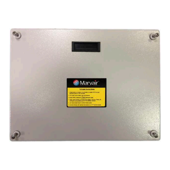
Comfort mode push button. Touch to enable (green) and touch again to disable (grey). When enabled, system will drop the cooling temperature set point to 77°F for a period of 60 minutes. Menu push button: Home • Active Alarms • Event Log •... -
Page 23: Dac/Wac Unit Control
5.5 DAC/WAC Unit Control Provides functions to control the operation of the equipment associated with the DAC/WAC unit. Figure 24: DAC/WAC Unit Control Web Page Auto Auto mode push button (default auto). Touch to disable auto (grey) and touch again to enable auto (green). Note that re-selecting auto will automatically de-energize any equipment that was energized while auto mode was disabled. -
Page 24: Dx Menu
5.6 DX Menu For system configurations with dual DX HVAC units shows status of both DX units. Figure 25: DX Unit Menu Web Page DX1/DX2 DX 1/DX 2 unit status: : Power on. • : Communications alarm or power failure alarm. •... -
Page 25: Dx Unit Control
5.7 DX Unit Control Provides functions to control the operation of the equipment associated with the DX unit. Figure 26: DX Unit Control Web Page Auto Auto mode push button (default auto). Touch to disable auto (grey) and touch again to enable auto (green). Note that re-selecting auto will automatically de-energize any equipment that was energized while auto mode was disabled. -
Page 26: Blower Settings
5.8 Blower Settings To change any of the set point fields, simply press the left (decrease) or right (increase) arrow. After a period of 60 minutes any fields that have been changed will revert to their default values. The graph above the set point controls provides a pictorial representation of the set point values versus the blower speed. -
Page 27: Sensor Info
5.9 Sensor Info Displays the temperature and relative humidity readings from the inside and outside sensors. The outside sensor is housed within the DAC/WAC unit. There are no user-adjustable fields on this page. Figure 28: Sensor Info Web Page Inside Sensor 1 Temp Inside temperature (range 32°F to 122°F) Inside Sensor 1 RH Inside relative humidity (range 0% to 100%) -
Page 28: Alarms
5.10 Alarms Displays the quantity and type of any active alarms in the controller. There are no user-adjustable fields on this page. Figure 29: Alarms Web Page 5.11 Event Log Displays log of system events, which include alarm set/resets, user-entered changes, and periodic sensor readings. Entries are ordered by date/time and retained for five years. -
Page 29: System Config
5.12 System Config Provides functions to set the date/time, select the system configuration, and initialize the shelter FA code. Note that the default settings in System Configuration section are the AT&T-mandated setup for the DAC/WAC with supplemental DX unit and no further re-configuration is required. The AT&T RAN Support Program Office should authorize changes to these fields. - Page 30 Figure 32: System Config Web Page – Part Two System Configuration HVAC 1 Interface Communications interface to HVAC unit 2: HVAC 2 Interface CoolLinks™ DX • Hardwired DX (default) • Note that changing the interface type requires a controller restart and the technician is prompted to confirm or cancel the request.
-
Page 31: System Info
5.13 System Info Displays system software versions and contact information. There are no user-adjustable fields on this page. Figure 33: System Info Web Page NG-IOM-ATT Release 1.2 July 12, 2019... -
Page 32: Extended System Config Options
5.14 Extended System Config Options When connected to the controller from a laptop rather than a smart phone two additional support functions are available to the technician on the System Config web page. These functions allow the technician to download operational and event log data from the controller, or to update the controller software. - Page 33 Click this push button to download and save the detailed system-level Update diagnostics file associated with the last software update. This file, Update Results.txt, may be requested by Marvair customer support to help diagnose issues with software updates. NG-IOM-ATT Release 1.2...
-
Page 34: Functional Test Procedure
Chapter 6 FUNCTIONAL TEST PROCEDURE 6.1 Pre-Test Checklist The NextGen CoolLinks™ system can be functionally tested with the controls and features provided by the system and without the need for additional test equipment. Note that all of the individual equipment components of the DAC/WAC and HVAC units can be exercised separately through the use of manual functions from the controller web page. -
Page 35: Smoke Alarm
6.4 HVAC Electric Heating Set the DAC Blower Low Speed Enable (see section 5.8) to 10°F above indoor air temperature and the • Heating Set Point Temp (see section 5.4) to 5°F above indoor air temperature to force HVAC mechanical heating. -
Page 36: Rbs Hvac1 Fail Alarm
6.8 RBS HVAC1 Fail Alarm At the five-port Ethernet router, unplug the Cat5e cable from the DAC/WAC unit (see section 4.4). • After approximately 60 seconds verify that a communications alarm for the DAC/WAC unit is an active • alarm in controller web page. Verify that the RBS HVAC1 Fail alarm is active at the NOC. -
Page 37: Marvair Contact Information
Marvair Contact Information For support information, please see the Marvair Product Support Contact List on the customer portal: https://airxcel.com/marvair/sales-support/marvair-customer-portal-login NG-IOM-ATT Release 1.2 July 12, 2019...
Need help?
Do you have a question about the CoolLinks NextGen and is the answer not in the manual?
Questions and answers