
Summary of Contents for ETAS ES1000.3
- Page 1 (217) 352-9330 | Click HERE Find the ETAS ES1000.2 at our website:...
- Page 2 ES1000.3 Housing ES1050.1 Battery Pack User’s Guide Artisan Technology Group - Quality Instrumentation ... Guaranteed | (888) 88-SOURCE | www.artisantg.com...
- Page 3 Copyright The data in this document may not be altered or amended without special notification from ETAS GmbH. ETAS GmbH undertakes no further obligation in relation to this document. The software described in it can only be used if the customer is in possession of a general license agreement or single license.
-
Page 4: Table Of Contents
Attaching the ES1000.3 ........ - Page 5 Remote Control using ES1120.x / ES1130.x in Slot 1 of the ES1000.3 Housing ........32 5 Technical Data .
- Page 6 ES1000.3 Housing ........
- Page 7 Contents Artisan Technology Group - Quality Instrumentation ... Guaranteed | (888) 88-SOURCE | www.artisantg.com...
-
Page 8: Introduction
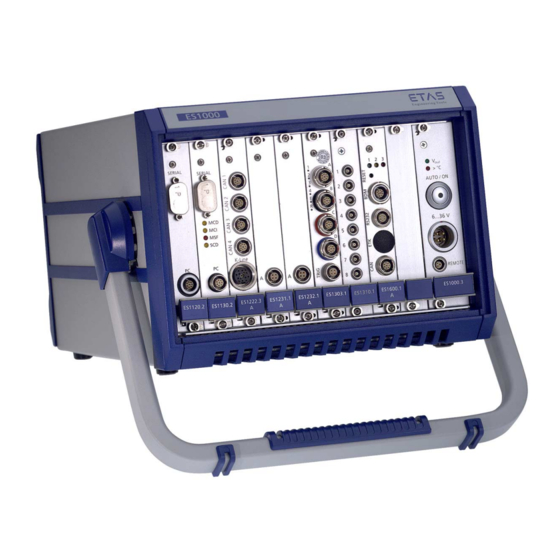
Overview 1.1.1 ES1000.3 Housing The ES1000.3 Housing with a VME64x backplane and power supply is the basis of ETAS’ modular ES1000.3 experimental system. Rapid-prototyping as well as test and calibration applications can be run with the relevant ETAS interface boards of the ES1000 system. -
Page 9: Es1050.1 Battery Pack
ES1050.1 Battery Pack 1.1.2 ES1050.1 Battery Pack The number of possible uses increases if the ETAS ES1000.3 experimental sys- tem is combined with an optional ETAS ES1050.1 Battery Pack: • power is supplied to the experimental system making the system inde- pendent of the vehicle power supply or an external power supply and •... -
Page 10: Block Diagram
The ETAS ES1050.1 Battery Pack is mounted directly on the ES1000.3 Housing creating one mechanical unit. Block Diagram The block diagram in Fig. 1-3 on page 9 shows the functions of the ES1000.3 Housing when used with an ES1050.1 Battery Pack. temperature ES1050.1... - Page 11 Introduction Artisan Technology Group - Quality Instrumentation ... Guaranteed | (888) 88-SOURCE | www.artisantg.com...
-
Page 12: Es1000.3 Housing
Note The VME64x standard is only fulfilled to a certain extent as the 3.3 V supply voltage is not provided. A slot is reserved for the power supply on the right-hand side of the ES1000.3 Housing. ES1000.3 Power Supply The ES1000.3 Housing power supply is also suitable for all automotive require- ments. -
Page 13: Control Elements
The ”AUTO / ON” switch on the front panel is used to switch between the operating modes automatic and normal of the power supply. The LED display in the operating mode switch (”AUTO / ON”) shows the oper- ating status of the ES1000.3 Power Supply (see section 2.3.2 on page 12). 2.3.2 Display Elements There are two LED displays on the front panel of the power supply control unit ) and (>... -
Page 14: Power Supply Interface
Note To guarantee a wide input voltage range, the power supply interface on the power supply control unit of the ES1000.3 is not fused. It must therefore be fused externally. The power supply interface on the ES1000.3 Power Supply Control Unit is con- nected to a voltage source using the K100 cable. -
Page 15: Automatic Overcurrent Deactivation
LED on the front panel of the power supply control unit goes out. 2.3.5 Remote Interface If the ES1000.3 Power Supply is in automatic mode, the remote interface can be used to activate/deactivate the power supply (see section 4.3.3 on page 29). Note The remote interface cannot be used to switch the ES1000.3 Power Supply... -
Page 16: Attaching The Es1000.3
If you are operating the device using a battery pack and the securing strap is attached to the ES1000.3 Housing as shown in Fig. 2-2 on page 15, it is possi- ble to change the battery pack without removing the securing mechanism. - Page 17 ES1000.3 Housing Artisan Technology Group - Quality Instrumentation ... Guaranteed | (888) 88-SOURCE | www.artisantg.com...
-
Page 18: Es1050.1 Battery Pack
On the front of the battery pack, there is a ”Battery ON” switch which, together with the ”AUTO / ON” switch on the ES1000.3 Power Supply, is used to activate battery operation of the ES1000.3 (see section 4.3.5 on page 30). -
Page 19: Battery Pack Interface
Assembly You do not need any tools to mount the battery pack on the ES1000.3 Hous- ing. The mechanical connection establishes all necessary electrical connections between the ES1000.3 Housing and the ES1050.1 Battery Pack simulta- neously. -
Page 20: Preparing The Es1000.3 Housing
3.2.1 Preparing the ES1000.3 Housing Fig. 3-3 Preparing the ES1000.3 Housing To prepare the ES1000.3 Housing 1. Switch off the power supply to the housing. Make sure that all devices connected to the housing by cable are switched off. When carrying out the steps listed below, look at Fig. -
Page 21: Connecting The Battery Pack To The Es1000.3 Housing
3.2.2 Connecting the Battery Pack to the ES1000.3 Housing Fig. 3-4 Connecting the Battery Pack to the ES1000.3 Housing To connect to the ES1000.3 Housing 1. Position the battery pack above the housing as shown in Fig. 3-4 on page 20. -
Page 22: Dismantling
Fig. 3-5 Snapping in the Battery Pack Guide Pins Dismantling You do not need any tools to remove the battery pack from the ES1000.3 Housing. Interrupting the mechanical connection simultaneously disconnects all electrical connections between the ES1000.3 Housing and the ES1050.1 Battery Pack. -
Page 23: Closing The Es1000.3 Housing
The battery pack and the housing are now mechanically separated. All electrical connec- tions between the ES1000.3 Housing and the ES1050.1 Battery Pack (socket on the top of the housing and a connector on the bottom of the battery pack) are disconnected simulta- neously. -
Page 24: Charging The Battery Pack
Charging at the Battery Pack Interface of the ES1000.3 Housing The ES1000.3 Power Supply automatically charges the ES1050.1 Battery Pack via the ES1000.3 battery pack interface as soon as an external voltage source is applied (automatic operation) or when the ES1000.3 is operating normally. -
Page 25: Charging With An External Charger
The current charge status is indicated by two LEDs on the front of the battery pack (see section 3.1.2 on page 17). Charging the battery pack at the battery pack interface of the ES1000.3 can only be prevented by •... - Page 26 The ES1050.1 Battery Pack must not be operated, charged or stored on one of its long narrow sides, either standing or lying. This also applies when the battery pack is mounted on the ES1000.3 Housing. Note If the battery pack is kept in storage for a long period of time, it should be recharged at least every 6 months.
- Page 27 ES1050.1 Battery Pack Artisan Technology Group - Quality Instrumentation ... Guaranteed | (888) 88-SOURCE | www.artisantg.com...
-
Page 28: Operation
Operation Inserting VMEbus boards Some VMEbus boards have to be configured before they can be inserted. For more information, consult the relevant board manual. Note The boards can only be configured and installed at a workplace that is pro- tected against static discharge. To insert a board 1. -
Page 29: Removing Vmebus Boards
Removing VMEbus boards Note The boards can only be removed at a workplace that is protected against static discharge. To remove a board 1. Switch off the power supply to the housing. Make sure that all devices connected to the housing by cable are powered off too. -
Page 30: Operating Modes Of The Es1000.3 Power Supply
Operating Modes of the ES1000.3 Power Supply 4.3.1 Overview The ES1000.3 Power Supply can be operated either in normal or automatic operating mode. In automatic mode, it is possible to control the ES1000.3 Power Supply remotely. Operation is also possible using an ES1050.1 Battery Pack. -
Page 31: Normal Operating Mode
Using a Battery Pack After the ES1050.1 Battery Pack has been mounted on the ES1000.3 Housing (see section 3.2 on page 18), the ES1000.3 system can be supplied with power by the battery pack. The ES1000.3 takes its power from the battery pack either •... -
Page 32: Remote Control Of The Es1000.3 Power Supply
ES1000.3. The ES1000.3 Power Supply is powered off. Remote Control of the ES1000.3 Power Supply There are two different ways of remotely controlling the ES1000.3 Power Sup- ply in ”AUTO” operating mode (automatic operation): • remotely using the ES1000.3 Power Supply Control Unit •... -
Page 33: Remote Control Using Es1120.X / Es1130.X In Slot 1 Of The Es1000.3 Housing
• When the power supply is remotely controlled using the Ethernet connection of the ES1120.x / ES1130.x master card (remote via Slot 1 of the ES1000.3), the Ethernet communication between the relevant master card and the con- nected PC is evaluated. If, for example, a connected PC is booted and an Eth- ernet link detected, the ES1000.3 Power Supply is activated via the VMEbus. -
Page 34: Technical Data
Technical Data ES1000.3 Housing 5.1.1 Fulfilled Standards and Norms • EN 50 081-1 • EN 55 022/B (IEC CISPR22) • EN 55 011/B (IEC CISPR11:1997) • EN 50 082-1 • EN 61 000-4-2 (IEC 61000-4-2) • EN 61 000-4-3 (IEC 61000-4-3) •... -
Page 35: General Data
5.1.2 General Data Mechanical Data Mechanical structure 19” housing Height 180 mm Width 235 mm Depth 360 mm Weight (only equipped with the 8.6 kg power supply) Backplane Standard VME64x No. of slots 9 slots each 4 HP wide for standard Euro- card-sized boards (100 mm x 160 mm) Compatibility Standard VMEbus... -
Page 36: Electrical Data
12 V : max. 1 A Residual ripple < 50 mV Note To provide a wide input voltage range, the power supply interface on the ES1000.3 Power Supply Control Unit is not fused. It must be protected exter- nally. 5.1.4 Pin Assignment Power Supply Interface Fig. - Page 37 Remote Interface Connector Fig. 5-2 Remote Interface Pin Assignment (Solder Side View) Function Locking of the remote interface Remote External operating voltage ground Remote Interface Connector LEMO FGG.OB.303.CLAD35 Service Interface Fig. 5-3 Service Interface Pin Assignment (Solder Side View) Description RxD Receive Data TxD Transmit Data DTR Data Terminal Ready...
-
Page 38: Es1050.1 Battery Pack
Description 6 and DSR Data Set Ready + DCD Data Carrier Detect RTS Request To Send CTS Clear To Data ES1050.1 Battery Pack 5.2.1 General Data Product Features Property of the Batteries used Battery type Lead acid cells based on absorbing glass matt technology (AGM) Operating mode Maintenance-free operation... -
Page 39: Electrical Data
Battery Pack Capacity Battery pack capacity 7 Ah with 24 V output voltage Charge Time After Complete Discharge Charging using ES1000.3 Power Sup- 12 to 16 hours Charging using external power supply Approx. 3.5 hours (at + 20° C) Technical Data... - Page 40 Discharge Behavior System Autonomy with Sample Configuration The ES1000.3 System combined with an ES1050.1 Battery Pack can be used independent of the vehicle power supply or an external power supply. The way of the equipment with interface boards and the ambient conditions determines the length of time of standalone operation.
-
Page 41: Cables
K100 Cable Wiring 5.3.2 RS232 Cable (Null-Modem Cable) Note The standard cable required for the update is not supplied by ETAS. Please contact your local specialist dealer or have the cable made based on the following information. Fig. 5-7 Pin Assignment (Solder Side) Technical Data Artisan Technology Group - Quality Instrumentation ... - Page 42 GND (5) (5) GND RxD (2) (2) RxD TxD (3) (3) TxD RTS (7) (7) RTS CTS (8) (8) CTS (4) DTR DTR (4) (6) DSR DSR (6) DCD (1) (1) DCD Side A Side B Fig. 5-8 Null-Modem Cable Wiring Side A Connector Side B Connector SUB-D9 female...
- Page 43 Technical Data Artisan Technology Group - Quality Instrumentation ... Guaranteed | (888) 88-SOURCE | www.artisantg.com...
-
Page 44: Ordering Information
ES1000.3 Housing 6.1.1 Delivery Scope Order Name Short Order Name Number ES1000.3 Housing incl. power supply, ES1000.3 F-00K-103-091 power supply cable type 3 (K100), remote connector, documentation Note Please note that the ES1050.1 Battery Pack has to be ordered separately. - Page 45 Ordering Information Artisan Technology Group - Quality Instrumentation ... Guaranteed | (888) 88-SOURCE | www.artisantg.com...
-
Page 46: Etas Contact Addresses
Fax: +49 711 89661-105 Germany E-mail: sales@etas.de WWW: www.etasgroup.com North America ETAS Inc. 3021 Miller Road Phone: +1 888 ETAS INC Ann Arbor, MI 48103 Fax: +1 734 997-9449 E-mail: sales@etas.us WWW: www.etasgroup.com Japan ETAS K.K. Queen's Tower C-17F Phone:... - Page 47 Fax: +33 1 56 70 00 51 94588 Rungis Cedex E-mail: sales@etas.fr France WWW: www.etasgroup.com Korea ETAS Korea Co. Ltd. 4F, 705 Bldg. 70-5 Phone: +82 2 57 47-016 Yangjae-dong, Seocho-gu Fax: +82 2 57 47-120 Seoul 137-889 E-mail: sales@etas.co.kr Korea www.etasgroup.com...
-
Page 48: Index
Index Battery pack assembly 18 Accessories for ES1000.3 Housing 43 backup fuse 18 Assembly battery pack capacity 38 battery pack 18 charge time 38 Attaching the ES1000.3 15 charging 23 control elements 17 discharge behavior 39 Backplane 11 dismantling 21... - Page 49 Onboard power supply 13 delivery scope 43 Operating mode ETAS Contact Addresses 45 switching 29 External power supply 13 Operating modes of the ES1000.3 Power Supply 29 Operating position battery pack 25 Fan 14 Operation 27 Ordering information 43 Overcurrent deactivation 14 Index Artisan Technology Group - Quality Instrumentation ...
- Page 50 Pin assignment power supply 35 remote connector 36 service interface 36 Power supply 11 battery pack 14 control elements 12 display elements 12 features 11 fuse protection 13 onboard power supply 13 pin assignment 35 Recharging 25 Remote connector pin assignment 36 Remote control ES1120.x / ES1130.x 32 Remote interface 14...
- Page 51 Index Artisan Technology Group - Quality Instrumentation ... Guaranteed | (888) 88-SOURCE | www.artisantg.com...
Need help?
Do you have a question about the ES1000.3 and is the answer not in the manual?
Questions and answers