
Subscribe to Our Youtube Channel
Summary of Contents for Observator Instruments OMC-183-ML
- Page 1 OMC-183-ML Signal Conditioning Unit Installation & technical user manual Version 1.05 - 2019 Author: Observator Instruments...
- Page 2 Revisions: 0.1 (26-08-2016) Conversion of OMC-183 hardware into OMC-183-ML hardware Original OMC-183 manual version 3.17 was used to create this installation & technical user manual 0.2(26-09-2016) Review version 1.01 (25-10-2016) First release 1.02 (24-9-2018) Correction in connection OMC-938 display (page 12).
-
Page 3: Table Of Contents
2.10. OMC-443 T (4-20 A) ..............12 EMPERATURE SENSOR 2.11. OMC-938/939 D (RS422 / OMC-2900) ............... 12 ISPLAY COMMISSIONING THE OMC-183-ML ................. 13 3.1. PC / OMC-183-ML ..........13 ONNECTING YOUR LAPTOP TO THE 3.2....................... 13 EVICE STATUS 3.3. - Page 4 Page intentionally left blank OMC-183-ML Manual Page 4...
-
Page 5: Introduction
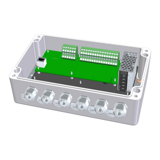
1. Introduction The OMC-183-ML is a signal conditioning unit. It is designed to read and feed multiple sensors and multiplex these signals to a serial signal. It does not log or store any data. Although the OMC-183 can be used in many applications, this manual assumes it is used for meteorological applications. -
Page 6: Installation
Installation The OMC-183-ML is designed to be used indoors. Find a suitable location with the required power and run your cables for all sensors. Typically you will find the following sensors: wind sensor (OMC-160, OMC-116, OMC-118, OMC-150 or OMC-115) temperature & humidity sensor (OMC-406, OMC-443 or OMC-448) -
Page 7: Connections
The in the lid of the casing and on the printed circuit board a description of the functionality of each pin is given. These descriptions are also used for MeteoLink products, therefore some functionalities are available in the OMC-183-ML software. Top row... -
Page 8: Omc-160 Wind Sensors (Nmea)
The Ultrasonic wind sensor got a standardized RS-422 output with NMEA protocol. 2 sensors can be connected. OMC-183-ML OMC-116 Sensor GND [SUP] Power GND SUPPLY Power 12-24V NMEA1_IN_A NMEA 0183 A NMEA1_IN_B NMEA 0183 B Recommended cable: shielded 2x2x0,75mm2 twisted pair OMC-183-ML Manual Page 8... -
Page 9: Omc-118 Ultrasonic Wind Sensor (Rs422 Nmea)
The junction box is part of the optional bracket OMC-122(-M). 2.5. OMC-150/158 EEx Wind sensor. The old OMC-158 is not compatible met the OMC-183-ML, however the new OMC-158-2 contains RS-422 NMEA output signal and is compatible. The wiring is similar to the OMC-160. OMC-183-ML Manual... -
Page 10: Oic-406 Temperature & Humidity Sensor
Temperature & Humidity sensor. The old OMC-406 is a less accurate sensor, and got two 4-20mA analog outputs. These signals can be connected to OMC-183-ML by using two of the analog current input ports for example current inputs 2 & 3:... -
Page 11: Omc-506 Single Barometric Pressure Sensor . (4-20 M A)
SUPPLY Power 12-24V Black 0-24mA_IN_1 4-20 mA out White The sensor can be build in the same housing as the OMC-183-ML Connections of sensor wires are identical. 2.9. OMC-9501 Barometric pressure sensor(s). (0 - 2.5V / 0 -5V) OMC-183-ML OMC-9501... -
Page 12: Omc-443 Temperature Sensor (4-20 M A)
OMC-938/939 Display (RS422 / OMC-2900) Recommended cable: shielded 2x0,75mm2 twisted pair The OMC-938 is usually connected to the RS422 output of the OMC-183-ML. With the OMC-183-ML it’s no longer optional to use current loop output. Reconfigure the OMC-938/9 to RS422 if required, see OMC-938/939 manual. -
Page 13: Commissioning The Omc-183-Ml
If you experience difficulties connecting with the device; Check if the LED’s are blinking, Check the wiring of the Tx/Rx or A/B wires; Check the data settings of your COM port. Note: The RJ-45 / Ethernet option is not active on the OMC-183-ML, theses LED’s are switched off. OMC-183-ML Manual... -
Page 14: User Settings Qnh & Qfe
(OMC-509) is used. The location of the pressure head is irrelevant for the sensor height! The sensor is preferable build in the same housing as the OMC-183-ML. According to the CAP-437 barometric pressure must be measured with a minimum of 2 sensors placed at the same location. -
Page 15: Menu Structure
Air temperature sensor (range: -30 - 70 C) 4: 4-20 mA Humidity sensor (range: 0 - 100 %) The OMC-183-ML will use 2 baro sensors as maximum, do not assign more (either current or voltage), since this could lead to unpredictable behavior! Commands 3-6: The 0-5 Voltage inputs need to be configured in order to convert the voltage into the right parameter. - Page 16 If the presented values are way of the expected values the old values of calibration will remain. Connect 0 mA reference, then press ENTER Connect 24 mA reference, then press ENTER Connect 0 Volt reference, then press ENTER Connect 5 Volt reference, then press ENTER OMC-183-ML Manual Page 16...
- Page 17 5 Volt value: 64309 Always use the ‘Q’ command “Save and exit menu” if you change anything. Without your changes might be lost once the power is switched off! After changing ‘baud rate’ reboot device as well. OMC-183-ML Manual Page 17...
-
Page 18: Eu Declaration Of Conformity
5. EU DECLARATION OF CONFORMITY OMC-183-ML Manual Page 18...
Need help?
Do you have a question about the OMC-183-ML and is the answer not in the manual?
Questions and answers