
Related Manuals for Steren STV-062


Summary of Contents for Steren STV-062
- Page 1 STV-062-V1.0-instr.pdf 23/08/16 5:06 p.m. STV-062 Soporte ultra delgado para pantalla LED / LCD 24 - 47” V1.0 Manual de Usuario 0816A...
- Page 2 STV-062-V1.0-instr.pdf 23/08/16 5:06 p.m. Antes de utilizar su nuevo producto, lea el siguiente instructivo • Este aparato NO está destinado para ser utilizado por personas con capacidades diferen- tes, a menos que cuenten con la preparación y supervisión adecuadas. • Este producto NO es un juguete; manténgalo fuera del alcance de los niños.
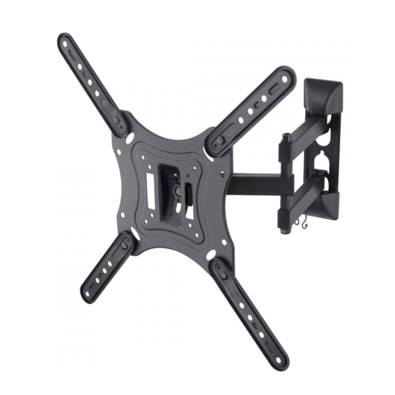
- Page 3 STV-062-V1.0-instr.pdf 23/08/16 5:06 p.m. A(x1) B(x2) C(x1) Soporte Protectores Sujetacables D(x4) E(x4) F(x4) Extensores Tornillos Tuercas (x4) Rondanas Tornillos Plásticas W-A (x3) W-B (x3) (x1) Rondana Tornillos Taquetes Contenido...
-
Page 4: Herramientas Necesarias
5:06 p.m. Herramientas necesarias Nivel de gota Steren no se hace responsable por daños materiales ni personales causados por mal uso o mala instalación. Es responsabilidad del usuario asegurarse de la correcta instalación y uso del producto, así como de su periódica revisión. - Page 5 STV-062-V1.0-instr.pdf 23/08/16 5:06 p.m. a) Sobre concreto 60mm (2.4”) Ø10mm (ø 3 /8”) √ Asegúrese de que los tornillos sobresalgan aproximadamente 3 mm de la superficie Instalación...
- Page 6 STV-062-V1.0-instr.pdf 23/08/16 5:06 p.m. b) Sobre madera 55mm (2.2”) Ø4.5mm (ø 3/16”) Recuerde que la madera debe estar en óptimas condiciones. No coloque el soporte sobre madera comprimida o húmeda. √ Asegúrese de que los tornillos sobresalgan aproximadamente 3 mm de la superficie...
- Page 7 STV-062-V1.0-instr.pdf 23/08/16 5:06 p.m. Colocar los extensores Elija alguna de las dos siguientes opciones para sujetar los extensores. Utilice los tornillos (E) y las tuercas (F) opción a) opción b) Instalación...
-
Page 8: Instalación De La Pantalla
STV-062-V1.0-instr.pdf 23/08/16 5:06 p.m. Instalación de la pantalla opción a) Utilice 4 tornillos (M-A / M-B) y las 4 rondanas (M-C) para fijar el soporte a la parte posterior de la pantalla. Los tornillos suministrados son de medidas estándar. Le recomenda- mos consultar el manual de instrucciones de su pantalla para obtener información acerca de los tornillos necesarios para montarla en un... -
Page 9: Montaje
STV-062-V1.0-instr.pdf 23/08/16 5:06 p.m. Montaje 1. Con ayuda de otra persona sostenga el soporte junto con la pantalla colocada previamente. Inserte el soporte en los tornillos previamente colocados en la pared . C oloque el tercer tornillo (W-A) y la rondana (W-C) para asegurar el soporte. - Page 10 STV-062-V1.0-instr.pdf 23/08/16 5:06 p.m. 2. Con ayuda de un desarmador de punta de cruz atornille hasta que el soporte quede firmemente colocado. En seguida coloque las tapas protectoras en ambos lados de la base como se muestra en la imagen.
- Page 11 STV-062-V1.0-instr.pdf 23/08/16 5:06 p.m. Ajuste del ángulo de visión +20° -20° Abroche el Afloje el Vuelva a sujeta cables seguro de apretar el para que rosca e incline seguro de queden la pantalla para rosca hasta seguros una mejor que el soporte los cables.
- Page 12 STV-062-V1.0-instr.pdf 23/08/16 5:06 p.m.
- Page 13 STV-062-V1.0-instr.pdf 23/08/16 5:06 p.m. STV-062 24 to 47” ultra slim LED / LCD TV stand V1.0 Instruction Manual 0816A...
- Page 14 STV-062-V1.0-instr.pdf 23/08/16 5:07 p.m. • Before using your product, please read the following instructions • This device cannot be used by people with different habilities, unless they have preparation and supervision. • This product is NOT a toy; keep it away from...
- Page 15 STV-062-V1.0-instr.pdf 23/08/16 5:07 p.m. A(x1) B(x2) C(x1) Support Protections Cable lead - through D(x4) E(x4) F(x4) Extenders Screws Nuts M6x14 (x4) M8x20 (x4) M-C (x4) Washer Screws Screws Plastic W-A (x3) W-B (x3) (x1) Screws Dowel Washer Content...
-
Page 16: Tools You May Need
Tools you may need Level drop Steren it is not responsible by materials or personal damage caused by improper use or improper installation. Is responsibility of the user to be sure of the correct installation and the use of the product, as well as of their constant revision. - Page 17 STV-062-V1.0-instr.pdf 23/08/16 5:07 p.m. a) Installation in concrete 60mm (2.4") ø 10mm (ø 3/8") √ Make sure the screws protrude approximately 3 mm from the surface Installation...
- Page 18 STV-062-V1.0-instr.pdf 23/08/16 5:07 p.m. b) Installation in wood 55mm (2.2”) Ø4.5mm (ø 3/16”) Remember: the wood must be in optimal conditions. Don’t place the support over compressed or wet wood. √ Make sure the screws protrude approximately 3 mm from the surface...
- Page 19 STV-062-V1.0-instr.pdf 23/08/16 5:07 p.m. Place the extensor Choose one of the following two options to hold the extenders. Use the screws (E) and nuts (F) Option a) Option b) Installation...
-
Page 20: Screen Installation
STV-062-V1.0-instr.pdf 23/08/16 5:07 p.m. Screen installation option a) Use 4 screws (M-A / M-B) and 4 washers (M-C) to secure the bracket to the back of the screen. The supplied screws are standard measures. We recommend consulting the instruction manual of your screen for information about the necessary screws for mounting on a support. - Page 21 STV-062-V1.0-instr.pdf 23/08/16 5:07 p.m. 1. With the help of another person hold the stand with the screen previously placed. Insert the bracket on the screws previously placed on the wall. P lace the third screw (W-A) and the washer (W-C) to ensure support.
- Page 22 STV-062-V1.0-instr.pdf 23/08/16 5:07 p.m. 2. Using a screwdriver, cross tip screw until the bracket is seated. Then attach the protective covers on both sides of the base as shown in the image. 3. Insert the cable lead - through Installation...
- Page 23 STV-062-V1.0-instr.pdf 23/08/16 5:07 p.m. +20° -20° Fasten the Loosen the Retighten the cable ties so screw lock and screw lock until that they are tilt screen for the bracket is safe better vision. secure. the cables. Installation...
- Page 24 STV-062-V1.0-instr.pdf 23/08/16 5:07 p.m.
Need help?
Do you have a question about the STV-062 and is the answer not in the manual?
Questions and answers