
Summary of Contents for ROEQ TR125
- Page 1 ROEQ TR125 Top Roller system Original User Guide (en) ROEQ TR125 Top Roller user guide V1.3...
- Page 2 In addition, the content of the document is subject to change without prior notice. Every precaution has been taken in the preparation of this manual. Nevertheless, ROEQ assumes no responsibility for errors or omissions or any damages resulting from the use of the information contained.
-
Page 3: Table Of Contents
3.2. ROEQ Top Roller ..........................14 ROEQ Top Roller installation ........................16 4.1. Unpacking and installing the ROEQ Top Roller System ..............16 4.2. Setting up SICK safety configuration ....................19 4.2.1. Connecting to the Sick safety system ..................19 4.2.2. - Page 4 Accessories for ROEQ Top Roller ......................43 5.1. Stand-alone docking station ......................43 Technical Specifications ........................... 44 6.1. Cargo specification .......................... 45 Maintenance ............................48 7.1. Regular cleaning and inspection ...................... 48 Declaration of conformity ........................49 ROEQ TR125 Top Roller user guide V1.3...
-
Page 5: Introduction
1. Introduction 1.1. Intended readership The purpose of this user guide is to support the system integrator in setting up the ROEQ Top Roller 25 for MiR 100 and ROEQ Top Roller 125 for MiR 200. The descriptions throughout the guide assumes a basic level of knowledge regarding the setup process of the MiR robot and software interface. -
Page 6: Safety
The notices referring to personal safety are highlighted in the manual by a safety alert symbol. The notices shown below are graded by signal words to indicate degree of danger. The ROEQ products are intended to be used with MiR100™/MiR200™ robots. Read the MiR manual carefully before commissioning the combined solution. -
Page 7: General Safety Instructions
The robot should not be driven over edges or in other ways operated irresponsibly. • Only use TR125 for transporting approved cargo Always comply with the cargo specifications outlined in section 6 - Technical Specifications. Risk of package dropping to the ground if moving the robot. - Page 8 • Where to place Avoid driving in areas with obstacles and always keep all drive paths clean and free for obstacles. Avoid placing docking stations on slopes. Always check weight/speed/slope conditions before commissioning. ROEQ TR125 Top Roller user guide V1.3...
-
Page 9: Notices
The ambient temperature in the robot’s environment must not exceed 50 degrees Celsius - 122 degrees Fahrenheit. • Avoid exposure of the robot to excessively humid or dry environment Risk of damage to the robot or robot components. ROEQ TR125 Top Roller user guide V1.3... -
Page 10: Safety Circuit
Using the ROEQ equipment does not overrule the safety circuit principle made by MiR. Same principles are valid after installation of ROEQ Top Roller and if a person or other moving object enters the safety zones of the robot, where the planner due to response time, errors etc. does not respond, the safety circuit will force the robot into emergency stop, and the robot stops immediately. -
Page 11: Preventing Accidents From Dangling Packages
2.7. Preventing accidents from dangling packages The ROEQ Top Roller extends the default safety system of the MiR robot by adding an additional source for providing emergency stops. The Top Roller uses this to issue emergency stops when there is a risk that packages may drop to the floor. -
Page 12: Preventing Accidents From Undesired Unload Of Packages
– See “Installing docking sensor” under section 4.5. 2.9. Safety system specifications The regulations and specifications regarding the MiR100™/MiR200™ safety system stated in the user guide supplied by MiR remains valid when installing the ROEQ Top Roller system. ROEQ TR125 Top Roller user guide V1.3... -
Page 13: Intended Use
ROEQ specific requirements stated in section 6, the limitations given by MiR apply. In particular, when moving cargo with the ROEQ TR systems, the user must take care in complying with the MiR payload and center-of-mass specifications. -
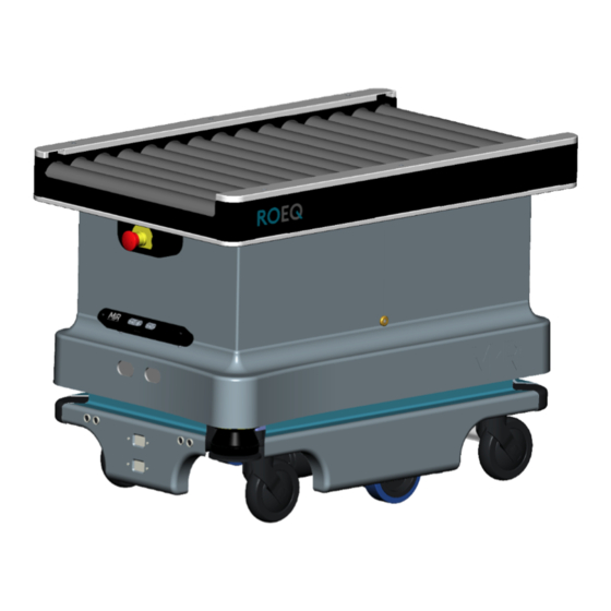
Page 14: Detailed Presentation
The ROEQ Top Roller works in conjunction with the software embedded on the MiR robot and acts as an extension of the robot’s autonomous capabilities. - Page 15 Pos. Description Pos. Description Front sensor Top Roller installation bolts Emergency stop button Top camera supplied by MiR ROEQ TR125 Top Roller user guide V1.3...
-
Page 16: Roeq Top Roller Installation
4. ROEQ Top Roller installation When installing the ROEQ Top Roller system on a MiR100™/MiR200™ the following steps must be performed: 1. Unpacking the ROEQ Top Roller system Section 4.1 2. Installation and connection of the Roeq Top Roller Section 4.1 3. - Page 17 Plug in the 4 pin and 10 pin connectors as well as the ethernet and Wi-Fi cable. Place the Top Roller unit on top of the conveyor base, while making sure not to damage the cables. ROEQ TR125 Top Roller user guide V1.3...
- Page 18 M3 bolts. Remove the strip restraining the cables from the conveyor base. Connect the conveyor base to the Top Roller by plugging in the Molex and JST connectors to their corresponding counterpart. ROEQ TR125 Top Roller user guide V1.3...
-
Page 19: Setting Up Sick Safety Configuration
This section describes the process for updating the SICK safety configuration on the MiR robot prior to using the ROEQ Top Roller. An updated safety configuration is required to enable the Top Roller in issuing emergency stops to the robot, when experiencing dangling packages. -
Page 20: Setting Up Com Settings
PC to the Sick system on the robot. Start the connection setup by clicking “Com settings”. The connection settings window will appear. A TCP/IP connection is required between the PC and the scanners. Click “Add TCP/IP connection profile”. ROEQ TR125 Top Roller user guide V1.3... - Page 21 IP of the safety system. Click “OK”. Click the check mark to test the connection. When the connection is accepted, mark the connection as default by double clicking the connection. Click “OK” to terminate the setup. ROEQ TR125 Top Roller user guide V1.3...
-
Page 22: Taking Backup Of Existing Laser Configuration (Recommended)
4.2.3. Taking Backup of existing laser configuration (Recommended) This section describes the procedure for taking backup of existing Sick configurations before transferring the ROEQ Sick configuration from the enclosed USB-drive. Step Instruction Illustration Click “Connect” to connect to the main Module. - Page 23 Repeat step 3 and 4 for taking backup of the rear scanner Double click the rear laser (S300.CPU1[0].EFI2.1) Finally select “Save as” in the project drop down window and save the original configuration on the PC. ROEQ TR125 Top Roller user guide V1.3...
-
Page 24: Uploading Roeq Safety Configuration To The Sick System
4.2.4. Uploading ROEQ safety configuration to the Sick system This section describes the procedure for transferring the ROEQ configuration from the enclosed USB-drive to the Sick system. It is highly recommended that the files stored on the enclosed USB-drive are saved in a local folder on the PC used for the SICK setup, before continuing with the following step. - Page 25 Module and the two S300 laser scanners. Make sure that both S300 scanners and the main Module are marked and click “OK”. The password for uploading the new safety zones is: SICKSAFE ROEQ TR125 Top Roller user guide V1.3...
- Page 26 “Release”. These can be saved if needed. Although the old main Module is verified, click “yes” to download the new configuration and run the new head device. ROEQ TR125 Top Roller user guide V1.3...
- Page 27 Verify the new checksum by clicking “yes”. ROEQ TR125 Top Roller user guide V1.3...
- Page 28 Mark the option for Authorized Client user group and click “OK”. Select “Upload and verify result” ROEQ TR125 Top Roller user guide V1.3...
-
Page 29: Generating Docking Points For The System
For further information, see Flexi Soft Gateway Operating Instructions chapter 4. 4.3. Generating docking points for the system For loading and unloading packages with the ROEQ Top Roller, the robot must first dock against a suitable external system to deliver or receive the packages being loaded or unloaded. - Page 30 For roll-and-lift systems the marker must be named: ROEQ_Docking station X lift conveyor Where Docking is spelled with a capital letter and X is an integer ID of the docking point. ROEQ TR125 Top Roller user guide V1.3...
- Page 31 Chose the type of product you need to create a docking point for – In this case choose “Conveyor” or “Lift Conveyor” depending on your product. Note: The remaining buttons “Cart”, “Rack”, etc. refers to other ROEQ products. ROEQ TR125 Top Roller user guide V1.3...
- Page 32 Please note that the docking station (docking points) generated here are only stored in the active map on the MiR robot. If multiple maps are used docking points must be generated in the individual maps/sites. ROEQ TR125 Top Roller user guide V1.3...
-
Page 33: Using The Roeq Top Roller Missions
Within the “ROEQ Conveyor” or “ROEQ Lift Conveyor” mission group, the ROEQ program has generated two missions for each docking position set up in section 4.3. Depending on the type of product you selected... - Page 34 • Do not unload packages without first docking to a suitable unloading station The ROEQ missions for loading and unloading packages are created with an initial docking procedure against one of the predefined docking positions. Do not attempt to modify these missions by removing the docking sequence.
-
Page 35: Mission Parameters
Top Roller, before the second package is seen by the front sensor. This will stop the conveyor and an error will be thrown with the message: “Conveyor Error: Conveyor already full” ROEQ TR125 Top Roller user guide V1.3... -
Page 36: Risk Of Dangling Packages
4.5. 4.4.3. Removing an emergency stop caused by dangling package There may be several reasons for the TR125 to issue an emergency stop based on the risk of a dangling package: • If the TR125 considers a package transfer to be complete, but the front sensors are still blocked. - Page 37 This process is to ensure proper placement of the cargo if the MiR is subsequently moved. The ROEQ button will stop lighting and it may be released. Clear the issued error in the MiR interface.
-
Page 38: Remarks
TR125 assumes that loaded package is too long to fit onto the conveyor. • If an e-stop is issued by a separate source other than the TR125, e.g. by the laser scanners, pressing the button will do nothing as power cannot be restored to the rollers or brake motors. -
Page 39: Docking Marker Behind Front Of External Station (Recommended)
Manually move the robot and Top Roller into the desired position for interfacing the external loading/unloading station. Important: Be sure to verify that the height of the external station matches that of the Top Roller. ROEQ TR125 Top Roller user guide V1.3... -
Page 40: Docking Position With Marker Aligned With Front Of External Station
0.35 m. Important: Be sure to verify that the height of the external station matches that of the Top Roller. Detect and name the docking marker as described in section Note: ROEQ TR125 Top Roller user guide V1.3... -
Page 41: Installing Docking Sensor Reflector
– To easy this process, the reflectors shipped along with the top roller, is installed on a bracket with the proper angle – The functionality is outlined in Figure 5: ROEQ TR125 Top Roller user guide V1.3... - Page 42 2. The light from the docking sensor is identified on the external unloading stations and the reflector is positioned on top of the light, such as to reflect the light back to the sensor: ROEQ TR125 Top Roller user guide V1.3...
-
Page 43: Accessories For Roeq Top Roller
5. Accessories for ROEQ Top Roller This section illustrates the available accessories compatible for the ROEQ Top Roller system. 5.1. Stand-alone docking station ROEQ TR125 Top Roller user guide V1.3... -
Page 44: Technical Specifications
6. Technical Specifications This section contains the general technical specifications for the ROEQ Top Roller system related to the dimensions and performance of the ROEQ Top Roller installed on MiR100™ or MiR200™. Dimensions Maximum length 925 mm Conveyor length 915 mm... -
Page 45: Cargo Specification
Note: The user must always comply with the MiR specifications for cargo dimensions, weight and load placement Further, the cargo must be fully opaque in the areas that passes directly in front of the sensors, in order for these to detect the cargo. ROEQ TR125 Top Roller user guide V1.3... - Page 46 Figure 6 System height when fully colapsed. Minimum cargo height. Figure 7 Loading area and cargo width and lenght requirements ROEQ TR125 Top Roller user guide V1.3...
- Page 47 Figure 8 Example of cargo with cut-outs in the bottom, and illustration on the height restrictions to these cut-outs. ROEQ TR125 Top Roller user guide V1.3...
-
Page 48: Maintenance
7. Maintenance This section describes the requirements for maintaining the functionality and performance of the ROEQ Top Roller system. NOTE: The stated intervals are indicative and depend on the operating environment and frequency of usage of the robot. 7.1. Regular cleaning and inspection This table gives an overview of maintenance tasks for all ROEQ products. -
Page 49: Declaration Of Conformity
ROEQ Top Roller. To be able to operate with a ROEQ Top Roller an updated safety software configuration needs to be installed on the robot.
Need help?
Do you have a question about the TR125 and is the answer not in the manual?
Questions and answers