
Subscribe to Our Youtube Channel
Summary of Contents for Sanwa KIT-8D
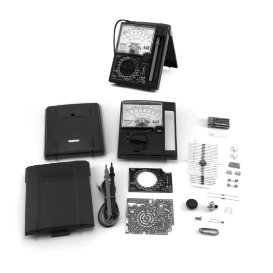
- Page 1 MULTITESTER KIT-8D Assembling Training for Circuit tester Instruction Manual for Assembling and Operation Procedures...
-
Page 2: Table Of Contents
Introduction Thank you very much for purchasing Sanwa Model KIT-8D Analog Multitester Kit. The KIT-8D is an analog multitester kit that we have developed for educational use through a wealth of our experiences and achievements. Although primarily designed as a kit, this product provides five modes including voltage and current, as well as high durability, allowing you to use it for a broad range of purposes. -
Page 3: I Instruction Manual
Safety Precaution – read before use Thank you for buying Sanwa Tester Kit <KIT- 8D>. The contents of ‘For Safe Use’, ‘Measurement’, and ‘Maintenance’ described in these operating instructions are particularly important. Read these items well before use for safe and correct operation. -
Page 4: Product Description
(Fig c) (Fig d) Note) Indication error may become larger if you use the meter in a standing Protection 9. Do not use the test leads when the envelope is damaged ; replace the leads with new Cover position because the meter is not (Fig c) (Fig d) placed horizontally. -
Page 5: Explanation Of Functions
How to read the scale plate � Measurement Scale to Scale Factor Range be used × 1k Ω × 1k Ω × 10 × 10 ① Ω × 1 × 1 DC300V × 1 AC300V × 1 DC0.3A × 0.001 DC30V ×... -
Page 6: Measuring Procedure
(Fig c) (Fig d) Note) Indication error may become larger if you use the meter in a standing Protection Cover position because the meter is not placed horizontally. Storage of the test leads Store the test leads in the storage space as illustrated in the right figure (Fig 1-3) when you do not use the device. -
Page 7: Measurement Of Dc Voltage
3 Measurement of DC voltage (DCV Measurable voltage : max. DC600V Warning 1. Never impress input signals that exceed the maximum measurable voltage of each range. 2. Be sure to carry out ‘range check’ for each measurement. 3. Do not switch to other ranges during measurement. 4. -
Page 8: Measurement Of Ac Voltage (Acv)
4 Measurement of AC voltage (ACV) Measurable voltage : max. AC600V Warning 1. Never impress input signals that exceed the maximum measurable voltage of each range. 2. Be sure to carry out ‘range check’ for each measurement. 3. Never carry out measurement when your hand is wet. 4. -
Page 9: Measurement Of Dc Current (Dca )
5 Measurement of DC current (DCA Measurable current : max. DC0.3A Warning 1. Do not impress voltage to the current measurement range. It may cause burns or electric shock. 2. Never apply input signals to the input terminal that exceed the maximum measurable current. -
Page 10: Measurement Of Resistance (Ω)
6 Measurement of resistance (Ω) Measurable resistance : max. 2MΩ Warning 1. Never impress voltage at resistance range. 2. Be sure to carry out ‘range check’ for each measurement. 3. Circuits to which voltage is applied cannot be measured. 4. Never carry out measurement when your hand is wet. 5. -
Page 11: Battery Check (1.5V)
7 Battery check (1.5V) Load resistance RL = 20Ω Warning 1. Be sure to carry out ‘range check’ for each measurement. 2. Do not switch to other ranges during measurement. 1) Objects to be measured Manganese dry batteries (SUM-1 / R20, SUM-2 / R14, SUM-3 / R6), alkaline batteries (LR20, LR14, LR6), etc. -
Page 12: Other Measurements
8 Other measurements An easy way of checking electronic components using the Ω range is introduced here. You can also check operation of each electronic component. See the following description for reference: a) Check of a diode Cathode mark The following procedures enable judgement of quality of a diode. For non-defective diodes, the meter will show a large deflection in the forward direction while deflection in the reverse direction will be negligible. - Page 13 Judgement The position of the needle : Deflection of the needle indicator for forward direction left side : ∞ direction ; Deflection of the needle indicator for reverse direction right side : 0 Ω direction Non-defective Short-circuit Wire breakage light will be emitted light will not be emitted light will not be emitted at forward direction...
-
Page 14: Maintenance
d) Check of a capacitor The meter also offers a way to check relatively large-capacity capacitors such as electrolytic capacitors. When the test pins are connected, the needle indicator will move because of the charging current of the capacitor and then return gradually to the origin. -
Page 15: Calibration
2 Calibration Warning Check and calibrate the product at least once a year for safety and maintenance of accuracy. Inquire with the distributors or the selling agencies to request check up and calibration. 3 Replacing the fuse and batteries Warning 1. -
Page 16: Storage
2) Replacement of the fuse Warning Use a fuse of the same rating for safety and maintenance of performance. (Place an order to our company if it is difficult to obtain.) The rating of the fuse used 0.5A / 250V (5.2 mm in diameter, 20 mm length, in a glass tube ; rupturing capacity : 300A) If you impress lamp line voltage (100V) etc. -
Page 17: Troubleshooting
Inquiries Make inquiries to our company for questions about the product : Tokyo Headquarter : TEL (03) 3251-0941 FAX (03) 3256-9740 E-mail : exp_sales@sanwa-meter.co.jp Web site of Sanwa Electric Instrument Co., Ltd. : http://www.sanwa-meter.co.jp... -
Page 18: Specifications
General Specifications AC Recrifier Form Half-wave rectifier form Meter type Internal magnet type. Taut band meter Accuracy Assurance Temperature / 1-8 Specifications 21 ~ 25°C 75%RH max. No condensation Humidity range Operating Temperature 3 ~ 43°C 80%RH max. No condensation ... -
Page 19: Basic Knowledge On Testers (Circuit Testers)
II Basic knowledge on testers (Circuit testers) 2-1 What is a tester? A tester (circuit tester), as the name suggests, is a measuring instrument designed to be very convenient for the check of circuits. The device has a structure that enables vast varieties of measurement including voltage, electric current and resistance by change of connection of the test leads or switching of the rotary switch, though it is not suitable for precise measurement in view of circuitry. -
Page 20: Structure Of A Tester
2-3 Structure of a tester A tester consists basically of the meter unit that indicates the electric charge, the resistor unit that magnifies the scale, the rectifier unit (diodes) that converts alternating current into direct current, and the battery unit that supplies power for measurement of resistance. Circuit components such as diodes and fuses are combined in addition to the units described above as protection circuits in view of safety. - Page 21 4 Zero Ω adjuster A carbon variable resistor is used for the zero Ω adjuster. The variable resistor of a tester has a role to minimize measurement errors by compensating the voltage change (wear and tear) of the internal batteries with a circuit. (Symbol) (Symbol) 5 Capacitor...
-
Page 22: Ohm's Law
2-4 Ohm’s law An understanding of Ohm’s law and calculation of effective resistance will provide understanding of the circuit of a tester to some extent. Three equations shown below express the relationship between electric quantities, i.e. voltage E [V], current I [A], and resistance R [Ω] : ………. -
Page 23: Prefix
2-6 SI prefix Prefixes are used in the indication and calculation of electric quantities such as voltage [V] when it is not easy to handle numbers too large or too small. It is important to adopt the same unit when calculating. Use of exponential expressions (e.g. - Page 24 − − Ω Transformation of (10) gives ..…... (11) • • ⎛ ⎞ − ⎜ ⎟ From (10), …… (12) • ⎝ ⎠ We can obtain the following equation by defining that − (where “n” is the magnification factor) : ……..
-
Page 25: 2-9 Rectification Circuit
2-9 Rectification circuit Testers have a structure that allows them to measure alternating current as well as direct current. Here is a simple explanation of rectification circuit that converts alternating current into direct current. a) Half - wave rectification Fig 2-20 (b) Full - wave rectification There are broadly two kinds of rectification circuits as illustrated in Fig 2-20. -
Page 26: Principle Of An Ohm Meter
2-10 Principle of an ohm meter (Known Resistance) (Known Resistance) , the electric current that will flow through adjuster adjuster the circuit when the SW is turned on in the circuit designated in Fig 2 - 23, is ………… (23) When the SW is turned off, R will be included in the circuit in serial and hence... -
Page 27: Color Code And Rating Code
2-11 Color code and rating code There are certain agreements on the method of indication for resistors and capacitors. Color code and rating code are described in this section. Color code is mainly used for resistors, while rating code is used for capacitors. Example of indication of a precision resistor ±... -
Page 28: Tester Assembly
III Tester Assembly Temperature most 3-1 Properties of soldering Phase diagram of Sn-Pb solder suitable for soldering (temperature higher by 50 - 60°C than ACE) As seen in the tin-lead phase diagram, the conditions around point C are beneficial for Liquid soldering of electronic components that are Semifluid... -
Page 29: 3-3 Soldering Practice 3-4
3-3 Soldering practice Patterns for KIT - 8D has a small board for soldering exercise. soldering Deliver the solder into the part for soldering on exercise this board to practice soldering. Cut the part off after training. Do not use this part for practice if you use the optional buzzer kit. -
Page 30: Assembling And Wiring
3-5 Assembling and wiring 1 Caution for assembly and wiring Do not turn the switch knob before assembly. The ball and spring included inside may leap out. a) Read the cautions well and perform assembly and wiring in the order given. b) The panels are made of resin and may melt and deform when in direct touch with the solder iron. - Page 31 2-2 Bending of the lead wires of the components It is very convenient to bend the lead wires of the components using the small board when you mount the components to the printed board. Put the body of a resistor or a diode into the square hole of the small board as shown in Fig 3-5.
- Page 32 Note Take care not to overheat the board or apply too much solder when soldering. � Do not move the components until the solder is set. � 3 Mounting of capacitor a) When assembling in the order of the parts list or the circuit structure Insert the component into C1 of the printed board and mount it.
- Page 33 5 Installation of fuse holders Order Check Operation Insert the fuse holders from the solder side (green side) into the printed board and solder them. (See Fig 3-10) Note Be careful of the direction of the nails � Place to Printed Board Printed Board when inserting the fuse holders.
- Page 34 7 Installation of fuse Order Check Operation Mount a fuse on the fuse holders as shown in (Silk-screen the figure. (One of the two fuses included in printed side) the package is the spare fuse and will be (Solder side) installed in the later process.) Fig 3-13 Fig 3-13...
- Page 35 Installation of switch brush Order Check Operation Install the switch brush onto the range selector knob mounted on the panel. Switch brush Place to install Panel Range selector knob (inside) Fig 3-15 Turn the range selector knob to align the positions of Ⓐand Ⓑ as illustrated below. Direct the switch brush so that the mark on it comes to the upper-left side.
- Page 36 Assembly check (II) Installation of switch brush Inspection Corresponding Items to be checked Check Article Is the mark of the switch brush in the correct direction ? (See Fig 3-16) Do the contact points of the switch brush have the same height ? (They should not be crushed).
- Page 37 Hold the panel in your hands as illustrated below. Position the completed printed board roughly and put it onto the panel lightly. Note) Hold the panel in your hands when you fasten the board. Beginning from part Ⓐ of the figure below, push the nail with your thumb to the direction indicated by the arrow in the figure.
- Page 38 Note Adjust the length of the test leads so that the length from the outlet of the lead presser becomes the same for both red and black leads. Lightly pull the leads after arrangement of the leads to check if they do not come out. ⑬...
- Page 39 ⑮ Mounting of spare fuse Order Check Operation Insert the spare fuse into the spare fuse case on the panel. Spare fuse case Fig 3-27 Assembly check (III) Assembly of the panel Inspection Corresponding Items to be checked Check Article Are the red and black meter lead wires connected to M+ and M-, respectively ? ⑩...
- Page 40 Rear case ⑰ Attachment of name sticker Order Check Operation (Place to attach Attach the name sticker on the rear case in the sticker) the position designated in the figure and write your name on it. Fig 3-30 ⑱ Storage of the test leads Order Check Operation...
- Page 41 Fig 3-34 Fig 3-34 Installation of the range selector knob SW knob For KIT-8D, the range selector knob is already incorporated into the panel. In the case that the range selector knob has come off during assembly procedures, follow the...
- Page 42 C) Assemble in the order of the circuit structure Assembly procedures 1) Perform the processes , installation of the dial plate, and installation of ⑨ ⑬ the battery terminal in process ⑭ 2) After completion of the above processes, mount the components by referring to the processing procedures described in processes -2 and 3) Always displace the soldering of the meter lead out of the printed board and dismount...
- Page 43 Direct Current Voltmeter Mount R3 (3V), R4 (12V) and R17. Install R5 to R9, which are common with the multiplier of the alternating current voltmeter. Alternating Current Voltmeter The multiplier components, common with the direct current voltmeter, have already been mounted. Install rectifier diodes D1 and D2.
- Page 44 Battery Check The battery check circuit is the one th at R3 and R13 is added to the meter circuit. No wiring is needed since these are already mounted Switch Brush Position When viewed from the soldered surface. (patterned surface) How to displace the printed board Ω...
-
Page 45: Operation Test And Calibration
IV Operation test and calibration 4-1 Quick operation check The circuit of this product does not require adjustment. Assembly and wiring of the product � will simply provide the tolerance range described in the specifications. The product is thus ready to be used as a normal circuit tester after simple operation check. Operation check requires resistors (100 Ω... - Page 46 3 Check of the DCV range (observed value ; the value in the parentheses is the voltage of the battery included in this kit) DC 3V range : Measure the battery voltage and read the meter. (ca. 1.6V) DC 12V range : Measure the battery voltage and read the meter. (ca.
-
Page 47: Calibration Of The Tester
4-2 Calibration of the tester Calibration is carried out to see if the assembled tester satisfies the accuracy as in the specifications. If the tester passes this examination, a highly reliable measurement is promised when you use it. In the case that the tester does not show the performance described in the specifications, there is a need to check if the correct resistances are mounted at the specified positions. -
Page 48: Measurement Results
ε , the relative error that indicates how large the absolute error is compared to the true value, is ε − ε × × Relative error For example, when the scale reading was 105V and the true value is assumed to be just 100V in measurement of the 100V - alternating current at the AC 300V range, the error is −... -
Page 49: Summary Of The Results
2 Calibration of the ohm meter (indication) Reading of Reading of Relative Error × × Range the tester the standard ε = T’ - M’ (%) device (T) Ω × 1k 20k Ω Ω × 10 200 Ω Ω × 1 20 Ω... -
Page 50: Circuit Calculation Of The Tester
V Circuit calculation of the tester 5-1 Meter Circuit The meter used in the tester is a moving - coil type as described earlier. This moving coil is formed by rounding a copper wire of 0.02 - 0.04 mm thickness hundreds of times and it is therefore difficult to make a coil have a constant resistance value (internal resistance). -
Page 51: Dca Circuit
5-2 DCA Circuit = Measured Current Rm = Meter Circuit Resistance The equation (18) for a shunt is used in calculation of DC ammeter circuit. Ohm’s law also provides the way to calculate. DC60 μ A : from the equation (18) for a shunt, μ... - Page 52 1 DC3V − Ω × − • Ω × Ω 2 DC12V − Ω × − • Ω × Ω 3 DC30V Because the same circuit as ACV is used for DC30V to DC600V, a shunt R is incorporated in the meter circuit in make them have the same sensitivity with ACV (9k Ω...
-
Page 53: Acv Circuit
6 DC600V ′ − Ω × − • Ω × ≅ Ω Ω − Ω − Ω Ω (to two decimal places) 5-4 ACV Circuit The meter of a tester indicates the average value. From equation (21), (root mean square value) = 1.11 (average �... - Page 54 2 AC30V Ω × Ω − Ω − Ω Ω 3 AC120V Ω × Ω Ω − Ω − Ω Ω 4 AC300V Ω × Ω Ω − Ω − Ω Ω 5 AC600V Ω × Ω Ω − Ω −...
- Page 55 For the highest limit of the adjustable range of the battery voltage, E (max), on the contrary, the zero Ω adjuster will be adjusted to the full, 10k Ω (Point “c”). The internal resistance between Point “c” and the ⊝ terminal, Rc, is ×...
-
Page 56: Battery Check Circuit (1.5V)
The internal resistance between Point “b” and the ⊝ terminal is × Ω Ω × Ω Ω Ω Ω Ω Ω Ω (round off to the third decimal place) The equivalent internal resistance between the terminals, when the battery voltage is 3.2V, is hence Ω... -
Page 57: Kit-8D Type Circuit Diagram
The position of each graduation on the scale plate is determined for each voltage by calculation of what percentage of Im im corresponds to. KIT-8D Type circuit diagram For this product, KIT - 8D, the answer values obtained from the calculation so far may differ from the values of the resistors used in the actual circuit. - Page 58 ...
- Page 59 ...
- Page 60 ...
- Page 61 Buzzer Red lead Buzzer black lead Buzzer black lead Buzzer red lead Buzzer red lead ...
-
Page 63: Parts List Sheet
Parts list sheet Rated Value Place to stick Color code/symbol 4.12 kΩF Yellow Brown Red Brown Brown Orange Black Black Red 30 kΩJ Gold 54.2 kΩF Green Yellow Red Red Brown Red Orange Red Orange Brown 232 kΩF 102 kΩF Brown ... - Page 65 ...
- Page 66 ...
- Page 67 ⊚ ...
- Page 68 Sanwa Electric Instrument Co., Ltd. Head Office: Dempa Building, 2-4-4 Sotokanda, Class Chiyoda-ku, Tokyo 101-0021 Japan Phone: 81-3-3253-4871 Osaka Sales Office: 2-7-2 Ebisu-nishi, Naniwa-ku, Name Osaka City 556-0003 Japan Phone: 81-6-6631-7361 05-1810 2040 2040...
Need help?
Do you have a question about the KIT-8D and is the answer not in the manual?
Questions and answers