Table of Contents
Advertisement
Quick Links
Advertisement
Table of Contents

Summary of Contents for PPM ViaLiteHD Blue2 Link
- Page 1 ViaLiteHD Blue2 Link User Guide HRX-XX-8X-35-XXXXX CR4260 23/10/2019 Pulse Power & Measurement Ltd, 65 Shrivenham Hundred Business Park, Watchfield, Swindon, Wiltshire SN68TY, UK Tel +44 (0)1793 784389 Fax +44 (0)1793 784391 Email sales@vialite.com www.vialite.com...
- Page 2 HD-B -HRX-XX-8X-35-XXXXX ANDBOOK Instrument Care and Safety Information Please read the whole of this section before using your ViaLiteHD product. It contains important safety information and will enable you to get the most out of your Fibre Optic Link. Electrical Safety The ViaLiteHD chassis is a Safety Class 1 product (having metal case directly connected to earth via the power supply cable).
-
Page 3: Table Of Contents
HD-B -HRX-XX-8X-35-XXXXX ANDBOOK TABLE OF CONTENTS INTRODUCTION ..........................5 1.1.1 HRX-L1-8P-33-S1310 ........................5 1.1.2 HRU-G1-8P-10-S1310 ......................... 5 1.1.3 HRU-L3-8P-35-W1310-1550 ....................... 5 1.1.4 HRV-L3-8P-03 ..........................5 Blue2 Link............................... 5 Typical deployment ..........................5 Care of fibre optic connectors ........................ 6 SETTING UP AND UNDERSTANDING THE FIBRE OPTIC LINK ..........7 2.1.1 RF connectors .......................... - Page 4 HD-B -HRX-XX-8X-35-XXXXX ANDBOOK 3.17 RF isolation ............................33 3.17.1 RF isolation, Blue link and Yellow link cards mounted in other ViaLite enclosures ....33 3.18 2 Harmonic rejection .......................... 34 3.19 Typical system configuration with fixed gain modules ................. 35 3.20 Commissioning of a communications link ....................
-
Page 5: Introduction
RF analogue signals over long distances for the communications market. ViaLiteHD is a product brand manufactured by Pulse Power and Measurement Ltd (PPM). ViaLite Communications is a division of Pulse Power and Measurement Ltd (PPM). -
Page 6: Care Of Fibre Optic Connectors
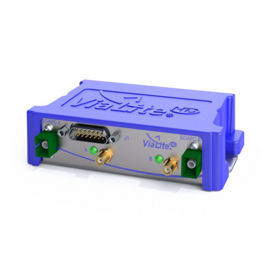
HD-B -HRX-XX-8X-35-XXXXX ANDBOOK The Blue2’s compact design means it can be used in existing customer equipment or easily fitted in smaller spaces, such as ship radomes/below-deck control rooms where space can be restricted. In addition to maritime, the Blue2 Link is suitable for use in the Broadcast, GPS or regular Satcom markets. -
Page 7: Setting Up And Understanding The Fibre Optic Link
2.1.1 RF connectors ViaLiteHD Blue2 Link is fitted with 50 Ohm female SMA connectors. The SMA connector is a semi-precision sub-miniature RF and microwave connector and to maintain performance up to 8GHz, ensure that when not in use, the supplied RF connector dust caps are fitted. - Page 8 HD-B -HRX-XX-8X-35-XXXXX ANDBOOK...
-
Page 9: Fibre Optic Cable & Connectors
HD-B -HRX-XX-8X-35-XXXXX ANDBOOK Fibre optic cable & connectors All ViaLiteHD RF modules use single-mode (9µm/125µm) cable terminated in a range of optical connectors detailed below. Cross-site fibre optic cables are available from ViaLite Communications as either standard patch leads or heavy-duty multicore cables. Angle polished (APC) and standard (PC) connector must not be confused. -
Page 10: Fc/Apc Connectors
HD-B -HRX-XX-8X-35-XXXXX ANDBOOK Using a dry cleaning tissue, dry the ferrule and clean the end face. Using the air duster, blow away any residue from the end of the connector. Module Female Receptacle Cleaning (only recommended if problems are being experienced) ... -
Page 11: Sc/Apc Connectors
HD-B -HRX-XX-8X-35-XXXXX ANDBOOK 2.2.5 SC/APC Connectors To connect SC/APC optical connectors follow these steps: Remove the plug protective cover. Align the connector keyway slot in the adaptor to the key of the plug. Gently push the plug-into the adapter until a click is heard and the connector locks. To disconnect follow these steps: ... -
Page 12: Using The Rf Link Module
HD-B -HRX-XX-8X-35-XXXXX ANDBOOK Using the RF link module 2.3.1 Connecting the module Connect the transmitter module to the power source, cross-site fibre optic cable and RF signals. The RF input signal applied to the signal connector should be within the maximum and minimum signal levels given in the datasheet. -
Page 13: Logic Interface, I2C
HD-B -HRX-XX-8X-35-XXXXX ANDBOOK 2.4.4 Logic interface, I2C Absolute maximum voltage rating -0.3 to +5.3V No damage Input, Logic Low (max) <1.5V Input, Logic High (min) >3.5V Output, Logic Low (max) <0.6V no load Output, Logic High (min) >4.3V no load Drive capability 1k ohms Short circuit protection... -
Page 14: Rf Connectors
HD-B -HRX-XX-8X-35-XXXXX ANDBOOK Maximum output voltage range 0 to +5V Short circuit protection 2.4.9 RF connectors Maximum RF input power, no damage +13 dBm continuous, 25 dBm (5 min max) Maximum usable input power Gain Setting Dependent (+1 dBm to -15 dBm typ) Maximum RF output power +15 dBm typ 2.4.10 Optical connections... -
Page 15: Blue2 Link Oem Module Connector
HD-B -HRX-XX-8X-35-XXXXX ANDBOOK 2.4.11 Blue2 Link OEM module Connector Pin Number Signal Name Description 1 12V_IN 12 Volt input, 11.5V to 13V nominal, 2A rated 2 TX/RX Alarm Alarm output from TX and RX modules 3 LD_MON Receive Light Level monitor 4 SDA I2C Data connection 5 SCL... - Page 16 HD-B -HRX-XX-8X-35-XXXXX ANDBOOK Blue2Link - Loom - P - 2RF Dual RX (c/w I2C & 232) 73931 15 way – D type +12V RX_ALARM (A) RX_RF_MON (A) SDA (A) SCL (A) LNA_FEED (A) RX_232_OUT (A) RX_232_OUT (B) RX_RF_MON (B) Pin 10 - NC SCL (B) GROUND (0V) SDA (B)
- Page 17 HD-B -HRX-XX-8X-35-XXXXX ANDBOOK Blue2Link - Loom - P - 2RF TRX-RS485/422/232 (No I2C) 15 way – D type +12V TX_ALARM (A) LD_MON (A) 422 IN+ (A) 422 IN- (A) LNA_FEED (A) TX_232_IN (A) RX_232_OUT (B) BUC_FEED (B) RTS(485) 485/422 OUT - (B) GROUND (0) 485/422 OUT+ (B) RLL_MON (B)
-
Page 18: System Integration
HD-B -HRX-XX-8X-35-XXXXX ANDBOOK System integration Link loss budget calculations The link gain (transmitter RF input level to receiver RF output level) depends on the following factors: Optical loss (due to connector insertion loss and optical fibre loss). Transmitter gain setting. ... -
Page 19: Gain Versus Frequency Response
HD-B -HRX-XX-8X-35-XXXXX ANDBOOK Gain versus frequency response The frequency response is not significantly affected by the gain setting of the attenuators used in ViaLiteHD. These have a flat frequency response over the full operating range of the product. Figures below are typical L-Band HTS modules responses. Gain plots versus TX gain (3dB steps) at RX gain 20dB Gain plots versus TX gain (0.5dB steps) at RX gain 20dB... -
Page 20: P1Db Versus Transmitter Gain
HD-B -HRX-XX-8X-35-XXXXX ANDBOOK Gain plots versus RX gain (3dB steps) at TX gain -11dB Gain plots versus RX gain (0.5dB steps) at TX gain -11dB P1dB versus transmitter gain The input P1dB of the link is dependent on the transmitter gain. Increasing the transmitter gain will decrease the link input P1dB.. - Page 21 HD-B -HRX-XX-8X-35-XXXXX ANDBOOK GPS input P1dB versus Tx gain at Rx gain 5dB Wideband input P1dB versus Tx gain at Rx gain 15dB Output P1dB versus TX gain setting (950/1200/1700/2150MHz) 950MHz 1200MHz 1700MHz 2150MHz TX gain setting (dB) L band output P1dB versus Tx gain at Rx gain 20dB...
-
Page 22: P1Db Versus Receiver Gain
HD-B -HRX-XX-8X-35-XXXXX ANDBOOK GPS output P1dB versus Tx gain at Rx gain 5dB Wideband output P1dB versus Tx Gain at Rx gain 15dB P1dB versus receiver gain The input P1dB of the link is not significantly affected by the receiver gain. Increasing the receiver gain have little effect on the link input P1dB, unless the output of the receiver approaches saturation. - Page 23 HD-B -HRX-XX-8X-35-XXXXX ANDBOOK GPS input P1dB versus Rx gain at Tx gain -5dB Wideband input P1dB versus Rx gain at Tx gain -15dB Output P1dB versus RX gain setting (950/1200/1700/2150MHz) 950MHz 1200MHz 1700MHz 2150MHz RX gain setting (dB) L band output P1dB versus Rx gain at Tx gain -11dB...
-
Page 24: P1Db, Key Observations
HD-B -HRX-XX-8X-35-XXXXX ANDBOOK GPS output P1dB versus Rx gain at Tx gain -5dB Wideband output P1dB versus Rx gain at Tx gain -15dB P1dB, key observations The P1dB is highly dependent on the gain setting of the transmitter, in most configurations the linearity of the link is dependent on compression of the laser and its associated amplifier, that are both situated after the gain control stage in the transmitter. -
Page 25: Noise Figure Versus Receiver Gain
HD-B -HRX-XX-8X-35-XXXXX ANDBOOK Noise Figure versus TX gain (RX gain +20dB) NF @ 950MHz NF @ 1200MHz NF @ 2150MHz TX gain setting (dB) Noise figure versus TX gain at frequency, RX gain 20dB Noise figure versus receiver gain The noise figure of the link is not significantly affected by the receiver gain. Increasing the receiver gain will slightly reduce the noise figure. -
Page 26: Spurious Free Dynamic Range
HD-B -HRX-XX-8X-35-XXXXX ANDBOOK 3.12 Spurious free dynamic range The dynamic range of the system is fundamentally set by the choice of laser and the optical loss. Transmitter and receiver gain can be used to optimise this for particular applications. All standard ViaLiteHD links are equipped with high power DFB lasers to give maximum dynamic range. - Page 27 HD-B -HRX-XX-8X-35-XXXXX ANDBOOK Phase Noise of a ViaLiteHD wideband link measured at 500MHz Phase Noise of a ViaLiteHD wideband link measured at 1000MHz...
- Page 28 HD-B -HRX-XX-8X-35-XXXXX ANDBOOK Phase Noise of a ViaLiteHD wideband link measured at 1500MHz Phase Noise of a ViaLiteHD wideband link measured at 2000MHz...
-
Page 29: Link Delay
HD-B -HRX-XX-8X-35-XXXXX ANDBOOK Phase Noise of a ViaLiteHD wideband link measured at 4000MHz 3.14 Link delay The ViaLiteHD link introduces a small amount of delay to the system, similar to the contribution of an amplifier. The typical delay contribution is shown below. You should also account for delay through RF and fibre cables as these are likely to be much higher than the delay in the link fibre optic modules. -
Page 30: Effects Of Temperature
HD-B -HRX-XX-8X-35-XXXXX ANDBOOK Group delay plot using a L-Band HTS Tx connected to an L-Band HTS Rx via a 0.5m fibre, 500 – 2500MHz All modules operating above L-Band HTS will be similar to the Ultra Wideband. Group delay plot using an Ultra Wideband Tx connected to an Ultra Wideband Rx via a 0.5m fibre, 10 –... - Page 31 HD-B -HRX-XX-8X-35-XXXXX ANDBOOK Link Temp (degC) Change of Link/Transmitter/Receiver gain at temperature, at 1.2GHz 950MHz 1200MHz 1700MHz 2150MHz Temp (degC) Change of link gain at temperature, versus frequency 950MHz 1200MHz 1700MHz 2150MHz Temp (degC) Change of transmitter gain at temperature, versus frequency...
-
Page 32: Effect Of Temperature On Noise Figure
HD-B -HRX-XX-8X-35-XXXXX ANDBOOK 950MHz 1200MHz 1700MHz 2150MHz Temp (degC) Change of receiver gain at temperature, versus frequency 3.16.2 Effect of temperature on noise figure The link noise figure will be increased as temperature increases. The graph below shows change in noise figure versus the room temperature noise figure. -
Page 33: Rf Isolation
HD-B -HRX-XX-8X-35-XXXXX ANDBOOK 950MHz 1200MHz 1700MHz 2150MHz Temp (degC) Change of link P1dB at temperature 3.17 RF isolation ViaLiteHD cards are designed to offer excellent isolation in operation, both isolation between the separate channels of dual modules and isolation from module to module in a chassis or enclosure mounted system. -
Page 34: Nd Harmonic Rejection
HD-B -HRX-XX-8X-35-XXXXX ANDBOOK 3.18 2 Harmonic rejection The second harmonic rejection is strongly dependent on how your link is configured; the chart below shows the typical performance in the following configuration. Link Type: L-Band HTS Device under test: HRT-L1-8R-33-S1310 HRR-L1-8R-03 Link gain: Set to default (-11/+20dB) Input Tone:... -
Page 35: Typical System Configuration With Fixed Gain Modules
HD-B -HRX-XX-8X-35-XXXXX ANDBOOK 3.19 Typical system configuration with fixed gain modules The diagram below illustrates a typical communications system configuration. RF feeds for Antenna SSPA and LNA ViaLiteHD chassis Patch cables Cable Termination box Cross site cable Cross site cable Cable Termination box Patch cables ViaLiteHD chassis... - Page 36 HD-B -HRX-XX-8X-35-XXXXX ANDBOOK 5. Confirm that the RF output from the receiver is correct (to within measurement accuracy). If the loss is much higher (> 3dB) than calculated, the most likely explanation is dirt on the optical connectors. If this is the case, clean each connection in turn until the required system gain is restored.
-
Page 37: Part Numbering
HD-B -HRX-XX-8X-35-XXXXX ANDBOOK Part numbering Part numbering matrix Note: Options are dependent on the module type. Not all combinations of options are available. Contact ViaLite Communications for more details. -
Page 38: Maintenance And Fault Finding Guide
HD-B -HRX-XX-8X-35-XXXXX ANDBOOK Maintenance and fault finding guide Refer to the following table that gives a list of commonly encountered problems and suggested solutions. Fault Possible Causes Solution Power LED does Power is not connected to the Connect mains power to the rear of the PSU. not illuminate. -
Page 39: Fcc Approval
HD-B -HRX-XX-8X-35-XXXXX ANDBOOK FCC Approval Information to the user of ViaLiteHD products: For a Class A digital device or peripheral, the following instructions are furnished to the user. This equipment has been tested and found to comply with the limits for a Class A digital device, pursuant to part 15 of the FCC Rules. -
Page 40: Product Warranty
HD-B -HRX-XX-8X-35-XXXXX ANDBOOK Product warranty ViaLite Communications guarantees its ViaLiteHD products and will maintain them for a period of three years from the date of shipment and at no cost to the customer. Extended warranty options are available at the time of purchase. Please note that the customer is responsible for shipping costs to return the module to ViaLite Communications.
Need help?
Do you have a question about the ViaLiteHD Blue2 Link and is the answer not in the manual?
Questions and answers