
Summary of Contents for General Photonics FPS-003
- Page 1 FPS-003 Fiber Phase Shifter Instruction Note Version 1.0 August 8, 2017 General Photonics Corp. Ph: (909) 590-5473 5228 Edison Ave. Fax: (909) 902-5536 Chino, CA 91710 USA www.generalphotonics.com Document #: GP-IN-FPS-003-10 Page 1 of 9...
-
Page 2: Table Of Contents
Table of Contents: CAUTION........................... 3 Section 1. Specifications: ....................4 Section 2. Overview......................5 Section 3. Operation Instructions:................... 7 Getting Started ....................7 Operation ......................7 Section 4. Technical Support ................... 9 Document #: GP-IN-FPS-003-10 Page 2 of 9... -
Page 3: Caution
CAUTION 1. Make sure that the polarity of the connection between the piezo driver and the FPS-003 electrical input is correct. Do not apply a negative voltage to the piezo. Document #: GP-IN-FPS-003-10 Page 3 of 9... -
Page 4: Section 1. Specifications
Electrical Interface Molex WM9131-ND or equivalent Operation Temperature 10 to 50° C Storage temperature −40° to 85° C Total Fiber Length 500 ±10 cm Dimensions 31.0 (L) x 31.0 (W) x 14.5 (H) mm Document #: GP-IN-FPS-003-10 Page 4 of 9... -
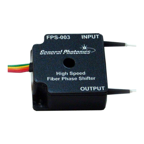
Page 5: Section 2. Overview
Negative Pin 4 Case Pin 1 is marked with a triangle on the connector. Optical Interface The FPS-003 has 2 fiber pigtails for the input and output signals. Input and output are interchangeable. Document #: GP-IN-FPS-003-10 Page 5 of 9... - Page 6 Mechanical Dimensions Figure 2 Mechanical dimensions of FPS-003, in mm Figure 2 shows the mechanical dimensions of the FPS-003, including the size and locations of mounting holes. For bottom mounting (screws inserted upwards from the bottom), use 5 #4-40 UNC L1/4 screws.
-
Page 7: Section 3. Operation Instructions
Adjust the piezo driver voltage to achieve the desired delay at the desired modulation frequency. See Figure 3 to Figure 5 for typical performance data for FPS-003s with different types of fiber. Turn off the electrical drive signal and light source when the FPS-003 is not in use. Document #: GP-IN-FPS-003-10... - Page 8 Figure 3 Typical performance data for 1310/1550nm SM FPS-003 (tested at 1550nm). Figure 4 Typical performance data for 1060nm SM FPS-003 (tested at 1064nm). Figure 5 Typical performance data for 780nm SM FPS-003 (tested at 1064nm). Document #: GP-IN-FPS-003-10 Page 8 of 9...
-
Page 9: Section 4. Technical Support
General Photonics is committed to high quality standards and customer satisfaction. For any questions regarding the quality and the use of the FPS-003, or future suggestions, please contact General Photonics Corporation at (909)-590-5473 (telephone) or (909)- 902-5536 (fax), or by e-mail at support@generalphotonics.com.
Need help?
Do you have a question about the FPS-003 and is the answer not in the manual?
Questions and answers