
Subscribe to Our Youtube Channel
Related Manuals for Stahl MCP/BG Series

Summary of Contents for Stahl MCP/BG Series
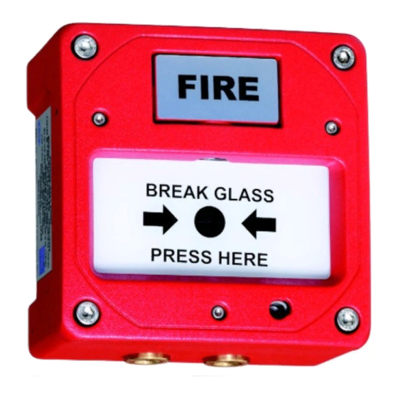
- Page 1 Operating instructions Additional languages r-stahl.com Flameproof Manual Call Points Series MCP/BG...
-
Page 2: Table Of Contents
Contents General Information ....................3 Manufacturer .......................3 Information regarding the Operating Instructions ..........3 Further Documents .....................3 Conformity with Standards and Regulations ............3 Explanation of the Symbols ................4 Symbols in these Operating Instructions ............4 Warning Notes ....................4 Symbols on the Device ..................5 Safety Notes .......................5 Operating Instructions Storage ................5 Personnel Qualification ..................5... -
Page 3: En En
• Data sheet For documents in additional languages, see r-stahl.com. Conformity with Standards and Regulations See certificates and EU Declaration of Conformity: r-stahl.com. The device has IECEx approval. For certificate please refer to the IECEx homepage: http://iecex.iec.ch/ Further national certificates can be downloaded via the following link: https://r-stahl.com/en/global/support/downloads/. -
Page 4: Explanation Of The Symbols
Explanation of the Symbols Explanation of the Symbols Symbols in these Operating Instructions Symbol Meaning Tips and recommendations on the use of the device Danger due to explosive atmosphere Danger due to live components Warning Notes Warnings must be observed under all circumstances, in order to minimize the risk due to construction and operation. -
Page 5: Symbols On The Device
Specialists who perform these tasks must have a level of knowledge that meets applicable national standards and regulations. Additional knowledge is required for tasks in hazardous areas! R. STAHL recommends having a level of knowledge equal to that described in the following standards: •... -
Page 6: 3.3 Safe Use
• Use the device in accordance with its intended and approved purpose only. • Always consult with R. STAHL Schaltgeräte GmbH if using the device under operating conditions which are not covered by the technical data. • Make sure that the device is not damaged. -
Page 7: Function And Device Design
Function and Device Design Function and Device Design DANGER Explosion hazard due to improper use! Non-compliance results in severe or fatal injuries. • Use the device only in accordance with the operating conditions described in these operating instructions. • Use the device only for the intended purpose specified in these operating instructions. -
Page 8: 5 Technical Data
Technical Data Technical Data Explosion Protection Global (IECEx) Gas and dust IECEx BAS 08.0089X Ex db IIC T6 Ta -55 to +70 °C Gb Ex tb IIIC T85 °C Ta -55 to +70 °C Db IP66 Europe (ATEX) Gas and dust Baseefa 08ATEX0269X E II 2 G Ex db IIC T6 Ta -55 to +70 °C Gb E II 2 D Ex tb IIIC T85 °C Ta -55 to +70 °C Db IP66... -
Page 9: Transport And Storage
Mounting / Installation Assembly via holes through the back box. For further technical data, see r-stahl.com. Transport and Storage • Transport and store the device only in the original packaging. • Store the device in a dry place (no condensation) and vibration-free. -
Page 10: Mounting And Installation
Mounting and Installation Mounting and Installation The device is approved for use in gas explosion hazardous areas of Zones 1 and 2 and dust explosion hazardous area of Zones 21 and 22 and in safe areas. DANGER Explosion hazard due to incorrect installation of the device! Non-compliance results in severe or fatal injuries. -
Page 11: Installation
Mounting and Installation Installation DANGER Explosion hazard due to open holes, unused cable entries and cable glands! Non-compliance can result in severe or fatal injuries. • Only use approved and flameproof (Ex d) cable glands. • When selecting cable entries, observe the thread type and thread size in the component documentation. - Page 12 Mounting and Installation The device is to be installed on a wall made from a suitable material! Comply with local directives and standards when selecting the installation location! Reassembling the enclosure • If removed, replace the PCB and screws. • Replace the front cover with the middle frame. Ensure that the retraining strap is not pinched in.
- Page 13 Mounting and Installation 7.3.4 Standard Devices Single-pole MCP, switch normally closed in standby / normally open in alarm 1 Cable connection (from left) 2 L / + 3 N / - Common 16835E00 Single-pole MCP, switch normally open in standby / normally closed in alarm 1 Cable connection (from left) 2 L / + 3 N / -...
- Page 14 Mounting and Installation 7.3.5 Standard Devices with Monitoring Resistors • Standard versions with monitoring resistors are only available with switch normally closed in standby / normally open in alarm. • Resistor values are to be selected by the system designer, depending on requirements.
- Page 15 Mounting and Installation 7.3.6 Standard Devices with LED Status Light There is an 820 ohm resistor which is in line with the LED. When activated, the LED together with the resistor will draw a current. On a 24 V DC system this current is approximately 30 mA.
- Page 16 Mounting and Installation Single-pole MCP, switch normally open in standby / normally closed in alarm 17567E00 • Ensure that the connector wires from switch and LED are correctly installed as per the schematic (see the following figure). Connector terminal Red wire for LED Black wire for LED Blue wire for switch Yellow wire for switch...
- Page 17 Mounting and Installation Two-pole MCP, switch normally closed in standby / normally open in alarm (independent circuits) 17567E00 • Ensure that the connector wires from switch and LED are correctly installed as per the schematic (see the following figure). Connector terminal Red wire for LED Black wire for LED Blue wire for switch...
- Page 18 Mounting and Installation Two-pole MCP, switch normally open in standby / normally closed in alarm (independent circuits) 17567E00 • Ensure that the connector wires from switch and LED are correctly installed as per the schematic (see the following figure). Connector terminal Red wire for LED Black wire for LED Blue wire for switch...
- Page 19 Mounting and Installation Single-pole MCP, switch normally open in standby/normally closed in alarm 17567E00 • Ensure that the lead wires from the switch and LED are correctly installed (see the following figure). Connection terminal Black wire for LED Blue wire for switch Yellow wire for switch Red wire for switch Red wire for LED...
-
Page 20: Commissioning
Commissioning 7.3.8 Earth Connection 16564E00 Commissioning DANGER Explosion hazard due to incorrect installation! Non-compliance results in severe or fatal injuries. • Check the device for proper installation before commissioning. • Comply with national regulations. Before commissioning, ensure the following: • Check the mounting and installation. •... -
Page 21: Operation
Operation Operation Manual Signalling Device Test • Insert the key. 16565E00 Trip an alarm: • Carefully turn the key clockwise until the alarm is triggered. 16567E00 Test completed: • Turn the key back to its home position. The manual signalling device is ready to be used again. -
Page 22: 9.2 Resetting The Manual Signalling Device
Operation Resetting the Manual Signalling Device Key components Mounting hinge for the glass Recess Recess Piston Lever under spring tension Pivot point for the glass Pivot point for the glass 16572E00 CAUTION Danger of cutting injuries due to broken glass! Non-compliance can result in minor injuries. - Page 23 Operation 16571E00 • Remove the front cover from the device. • Remove the broken glass pane. • Position the new glass pane (1) carefully, as shown in the figure. Important: The bottom corner of the glass pane must rest on the mounting hinge. •...
-
Page 24: Troubleshooting
• Insert the screws and tighten them. 16577E00 Troubleshooting If the error cannot be eliminated using the mentioned procedures: • Contact R. STAHL Schaltgeräte GmbH. For fast processing, have the following information ready: • Type and serial number of the device • Purchase information •... -
Page 25: 10.1 Maintenance
10.2 Repair DANGER Explosion hazard due to improper repair! Non-compliance results in severe or fatal injuries. • Repair work on the devices must be performed only by R. STAHL Schaltgeräte GmbH. 250318 / MCP60300110 Flameproof Manual Call Points 2021-01-26·BA00·III·en·02 Series MCP/BG... -
Page 26: 10.3 Returning The Device
• Only return or package the devices after consulting R. STAHL! Contact the responsible representative from R. STAHL. R. STAHL's customer service is available to handle returns if repair or service is required. • Contact customer service personally. • Go to the r-stahl.com website.
Need help?
Do you have a question about the MCP/BG Series and is the answer not in the manual?
Questions and answers