
Summary of Contents for CENTURION SYSTEMS CLAWS
- Page 1 TRAFFIC BARRIERS CLAWS - DIRECT DRIVE INSTALLATION MANUAL Centurion Systems (Pty) Ltd www.centsys.com...
- Page 2 Americas, Australia and the Pacifi c Centurion Systems (Pty) Ltd reserves the right to make changes to the products described in this manual without notice and without obligation to notify any persons of any such revisions or changes. Additionally, Centurion Systems (Pty) Ltd makes no representations or warranties with respect to this manual.
-
Page 3: Table Of Contents
Spike Module Assembly page 19 6.3. Re-assembling the Ramp Plates and Linkage Cover page 26 6.4. Integrating the SECTOR II with the CLAWS page 28 6.5. Completing the Assembly page 32 RHS Surface Mount - Opposing Direction of Travel page 33 7.1. - Page 4 13.2. Spike Module Assembly page 96 13.3. Preparing the Trench and Drainage System page 103 13.4. Re-assembling the Ramp Plates and Linkage Cover page 105 13.5. Integrating the SECTOR II with the CLAWS page 106 13.6 Completing the Assembly page 110 page 4...
- Page 5 114 14.3. Preparing the Trench and Drainage System page 121 14.4. Re-assembling the Ramp Plates and Linkage Cover page 123 14.5. Integrating the SECTOR II with the CLAWS page 124 14.6 Completing the Assembly page 128 LHS Flush Mount - Similar Direction of Travel page 129 15.1.
- Page 6 All installation, repair, and service work to this product must be done by a suitably qualifi ed person • Do not activate the CLAWS unless you can see them and can determine that the CLAWS are clear of people, pets, vehicles or any obstructions. •...
-
Page 7: Safety First Important Safety Instructions
Always check the obstruction detection system, and safety devices for correct operation • Neither Centurion Systems (Pty) Ltd, nor its subsidiaries, accepts any liability caused by improper use of the product, or for use other than that for which the automated system was intended •... - Page 8 Loop detectors, positioning is very important for the safety of the vehicle • X refers to the distance required between the loops and CLAWS for free-exit • Free-exit for uni-directional traffi c, X must be greater than 500mm from the CLAWS •...
-
Page 9: General Description
Clever modular design allows the CLAWS to be ordered ex-stock and can be confi gured into a variety of diff erent lengths. The orientation of the spikes can also be easily changed depending on the direction of the traffi... -
Page 10: Product Dimensions
SECTION 2 PRODUCT SPECIFICATIONS 2.2. Product Dimensions 2.2.1. Surface Mount 1000mm 1500mm 405mm 2905mm 2905mm 2.2.2. Flush Mount 1000mm 1500mm 385mm 2885mm 2885mm page 10 www.centsys.com... -
Page 11: Surface Mount Installations
TRAFFIC BARRIERS DIRECT DRIVE SURFACE MOUNT INSTALLATIONS Centurion Systems (Pty) Ltd www.centsys.com page 11 www.centsys.com... -
Page 12: Product Identifi Cation
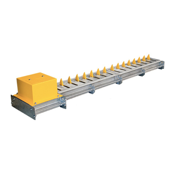
SECTION 3 PRODUCT IDENTIFICATION 3. Product Identifi cation CLAWS Direct Drive RHS Surface Mount - similar direction of travel illustrated FIGURE 1. PRODUCT IDENTIFICATION 1. Boom pole 5. Spikes 2. Spikes module assembly 6. Drive linkage assembly 3. Ramp plates 7. -
Page 13: Tools Required
SECTION 4 TOOLS REQUIRED Short Drive Arm Long Drive Arm Linkage Drive Shaft Bearing Housing Hold Down Bracket Con-rod Assembly Linkage Cover Plate Linkage End Cover Module End Cover 4. Tools Required • 13mm,17mm, and 19mm Spanners • Mallet • Ratchet •... -
Page 14: Introduction
And when driving up to the CLAWS Spikes, in the correct direction for traffi c fl ow, and the drive is installed on the left-hand side of the vehicle, it’s deemed a left-hand installation. -
Page 15: Spike Impact Direction
5.1.2. Spike Impact Direction The CLAWS Spikes are designed to take a much larger or more frequent impact in one direction. The spikes can be installed to face either towards oncoming traffi c (similar) or face towards traffi c (opposing) trying to enter from the wrong direction or lane. - Page 16 SECTION 5 INTRODUCTION Direction of normal traffi c fl ow FIGURE 7. RHS OPPOSED DIRECTION OF TRAVEL Direction of normal traffi c fl ow FIGURE 8. LHS SIMILAR DIRECTION OF TRAVEL Direction of normal traffi c fl ow FIGURE 9. LHS OPPOSED DIRECTION OF TRAVEL page 16 www.centsys.com...
-
Page 17: Rhs Surface Mount - Similar Direction Of Travel
SECTION 6 RHS SURFACE MOUNT - SIMILAR DIRECTION OF TRAVEL 6. RHS Surface Mount - Similar Direction of Travel 6.1. Confi guring the Drive Linkage Assembly for Right-hand Similar 6.1.1. Stripping the drive linkage assembly Drive linkage assembly M6x20 screw Linkage end cover STEP 1 FIGURE 10... - Page 18 SECTION 6 RHS SURFACE MOUNT - SIMILAR DIRECTION OF TRAVEL The unit is supplied with two drive arms, RHS and LHS (Section 6, Figure 16). Left-hand Side Orientation Right-hand Side Orientation LHS Installations RHS Installations FIGURE 16 Bearing Remove Short Grub Screw housing Drive Arm...
- Page 19 SECTION 6 RHS SURFACE MOUNT - SIMILAR DIRECTION OF TRAVEL Once assembled with the long drive arm, the layout should look as shown in Section 6, Figure 21. 1.5X 11 o’ clock VIEW A 6 o’ clock FIGURE 21 1. The drive arm must point towards the longer side of the drive linkage assembly (1.5x) 2.
-
Page 20: Spike Module Assembly
SECTION 6 RHS SURFACE MOUNT - SIMILAR DIRECTION OF TRAVEL STEP 12 Linkage cover plate Place the linkage plate back onto the drive linkage assembly without fastening the bolts. Check that the linkage cover plate is in the correct position and that there is ample clearance for the drive arm (Section 6, Figure 22). - Page 21 SECTION 6 RHS SURFACE MOUNT - SIMILAR DIRECTION OF TRAVEL 6.2.2. Attaching the drive linkage unit to the spike module Sandwich Linkage M12x25 plate unit bolt Spike module STEP 1 FIGURE 27 STEP 2 FIGURE 28 Take note of the orientation of the sandwich plate to the linkage unit before fi...
- Page 22 SECTION 6 RHS SURFACE MOUNT - SIMILAR DIRECTION OF TRAVEL 6.2.3. Bolting down the assembly to the ground M12 Rawl-bolts or Chem-bolts FIGURE 30 It is crucial that the surface it’s mounted on is a reasonably even surface as an uneven surface could result in an uneven binding of the spike shafts.
- Page 23 SECTION 6 RHS SURFACE MOUNT - SIMILAR DIRECTION OF TRAVEL Place the spikes into the down position (and the drive arm pointing upwards) to aid in the fi tment of all the shaft couplings. Dowel pin Groove Groove in shafts Dowel pin Bottom coupler Bottom coupler...
- Page 24 SECTION 6 RHS SURFACE MOUNT - SIMILAR DIRECTION OF TRAVEL 6.2.5. Proximity sensor installation Drive linkage end of the assembly 20mm PVC Conduit Far end of the assembly STEP 1 FIGURE 39 The length of the PVC conduit will be relative to the length of the spike modules and drive linkage unit combined.
- Page 25 SECTION 6 RHS SURFACE MOUNT - SIMILAR DIRECTION OF TRAVEL Use an appropriate PVC adhesive to bond all conduit lengths, access elbows and couplers to one another. 37x25mm 20mm PVC Coupler conduit 20mm PVC conduit 37x25mm PVC Coupler STEP 2 FIGURE 41 STEP 3 FIGURE 42...
- Page 26 SECTION 6 RHS SURFACE MOUNT - SIMILAR DIRECTION OF TRAVEL Proximity Threaded Proximity coupler shaft sensor assembly Proximity 37x25mm sensor bush PVC Coupler FIGURE 47. PROXIMITY SENSOR STEP 6 FIGURE 48 Drive linkage end of the assembly Far end of the assembly FIGURE 49 There should be ample cable left over on the drive linkage end, as the wiring will...
-
Page 27: Re-Assembling The Ramp Plates And Linkage Cover
SECTION 6 RHS SURFACE MOUNT - SIMILAR DIRECTION OF TRAVEL 6.3. Re-assembling the ramp plates and linkage cover Ramp plates M8x20 screw Ramp plates Spring Washer STEP 1 FIGURE 52 STEP 2 FIGURE 53 Leave out the four M8 screws and Spring Washers on the far end of the assembly as the module end cover will be assembled later. - Page 28 SECTION 6 RHS SURFACE MOUNT - SIMILAR DIRECTION OF TRAVEL It is imperative that the drive linkage cover plate is placed correctly. Make sure that there is clearance for the drive arm to swing through. If this plate is assembled back-to-front the drive arm won’t swing through and you will need to turn the plate around (Refer back to Section 6, Figure 22).
-
Page 29: Integrating The Sector Ii With The Claws
SECTION 6 RHS SURFACE MOUNT - SIMILAR DIRECTION OF TRAVEL 6.4. Integrating the SECTOR II with the CLAWS 6.4.1. Placing the SECTOR II into position SECTOR II SECTOR II Drive linkage cover plate Drive linkage Drive linkage Drive linkage unit... - Page 30 SECTION 6 RHS SURFACE MOUNT - SIMILAR DIRECTION OF TRAVEL 6.4.3. Inserting the Con-rod Con-rod SECTOR II STEP 1 FIGURE 66 STEP 2 FIGURE 67 Apply Lock-tite 243 to all the internal threads and torque both the M16x40 and M16x110 bolts to 40Nm (Steps 3 and 4) Do not place any body parts near the spikes as serious injury could occur;...
- Page 31 SECTION 6 RHS SURFACE MOUNT - SIMILAR DIRECTION OF TRAVEL 6.4.4. Adjusting the CLAWS spikes The CLAWS spikes will raise during this procedure! Con-rod top nut Con-rod base nut STEP 1 FIGURE 70 STEP 2 FIGURE 71 Turning the Con-rod clockwise or anti-closwise will raise or lower the spikes.
- Page 32 SECTION 6 RHS SURFACE MOUNT - SIMILAR DIRECTION OF TRAVEL With one person holding the barrier pole in the lowered position, adjust the spikes so that the spikes just touch the trench plate (Section 6, Figure 73). Con-rod Spike top nut Trench Plate Con-rod...
-
Page 33: Completing The Assembly
SECTION 6 RHS SURFACE MOUNT - SIMILAR DIRECTION OF TRAVEL 6.5. Completing the Assembly 6.5.1. Fitting the relay enclosure and its bracket SECTOR II SECTOR II Conrod Front brace plate Relay enclosure bracket Screws Relay enclosure Front brace bracket plate STEP 1 FIGURE 77 STEP 2... -
Page 34: Rhs Surface Mount - Opposing Direction Of Travel
SECTION 7 RHS SURFACE MOUNT - OPPOSING DIRECTION OF TRAVEL 7. RHS Surface Mount - Opposing Direction of Travel 7.1. Confi guring the Drive Linkage Assembly for Right-hand Similar 7.1.1. Stripping the drive linkage assembly Drive linkage assembly M6x20 screw Linkage end cover STEP 1 FIGURE 1... - Page 35 SECTION 7 RHS SURFACE MOUNT - OPPOSING DIRECTION OF TRAVEL The unit is supplied with two drive arms, RHS and LHS (see Section 7, Figure 7). Left-hand Side Orientation Right-hand Side Orientation LHS Installations RHS Installations FIGURE 7 Bearing Remove Short Grub Screw housing Drive Arm...
- Page 36 SECTION 7 RHS SURFACE MOUNT - OPPOSING DIRECTION OF TRAVEL Once assembled with the long drive arm, the format should look as shown in Section 7, Figure 12. 1.5X 1 o’ clock VIEW A 6 o’ clock FIGURE 12 1. The drive arm must point towards the longer side of the drive linkage assembly (1.5x) 2.
-
Page 37: Spike Module Assembly
SECTION 7 RHS SURFACE MOUNT - OPPOSING DIRECTION OF TRAVEL STEP 12 Linkage cover plate Place the linkage plate back onto the drive linkage assembly without fastening the bolts. Check that the linkage cover plate is in the correct position and that there is ample clearance for the drive arm (Section 7, Figure 13). - Page 38 SECTION 7 RHS SURFACE MOUNT - OPPOSING DIRECTION OF TRAVEL 7.2.2. Attaching the drive linkage unit to the spike module Sandwich Linkage plate unit M12x25 bolt Spike module STEP 1 FIGURE 18 STEP 2 FIGURE 19 Take note of the orientation of the sandwich plate to the linkage unit before fi...
- Page 39 SECTION 7 RHS SURFACE MOUNT - OPPOSING DIRECTION OF TRAVEL 7.2.3. Bolting down the assembly to the ground M12 Rawl-bolts or Chem-bolts FIGURE 21 It is crucial that the surface it’s mounted on is a reasonably even surface as an uneven surface could result in an uneven binding of the spike shafts.
- Page 40 SECTION 7 RHS SURFACE MOUNT - OPPOSING DIRECTION OF TRAVEL Place the spikes into the down position (and the drive arm pointing upwards) to aid in the fi tment of all the shaft couplings. Dowel pin Groove Groove in shafts Dowel pin Bottom coupler Bottom coupler...
- Page 41 SECTION 7 RHS SURFACE MOUNT - OPPOSING DIRECTION OF TRAVEL 7.2.5. Proximity sensor installation Drive linkage end of the assembly 20mm PVC Conduit Far end of the assembly FIGURE 30 The length of the PVC conduit will be relative to the length of the spike modules and drive linkage unit combined.
- Page 42 SECTION 7 RHS SURFACE MOUNT - OPPOSING DIRECTION OF TRAVEL Use an appropriate PVC adhesive to bond all conduit lengths, access elbows and couplers to one another. 20mm PVC conduit 20mm 37x25mm conduit PVC Coupler Linkage Frame 37x25mm PVC Coupler STEP 2 FIGURE 32 STEP 3...
- Page 43 SECTION 7 RHS SURFACE MOUNT - OPPOSING DIRECTION OF TRAVEL Proximity Threaded Proximity coupler shaft sensor assembly Proximity 37x25mm sensor bush PVC Coupler FIGURE 38. PROXIMITY SENSOR STEP 6 FIGURE 39 Drive linkage end of the assembly Far end of the assembly FIGURE 40 There should be ample cable left over on the drive linkage end, as the wiring will...
-
Page 44: Re-Assembling The Ramp Plates And Linkage Cover
SECTION 7 RHS SURFACE MOUNT - OPPOSING DIRECTION OF TRAVEL 7.3. Re-assembling the ramp plates and linkage cover Ramp plates M8x20 screw Ramp plates Spring Washer STEP 1 FIGURE 43 STEP 2 FIGURE 44 Leave out the four M8 screws and Spring Washers on the far end of the assembly as the module end cover will be assembled later. - Page 45 SECTION 7 RHS SURFACE MOUNT - OPPOSING DIRECTION OF TRAVEL It is imperative that the drive linkage cover plate is placed correctly. Make sure that there is clearance for the drive arm to swing through. If this plate is assembled back-to-front the drive arm won’t swing through and you will need to turn the plate around (Refer back top Section 7, Figure 13).
-
Page 46: Integrating The Sector Ii With The Claws
SECTION 7 RHS SURFACE MOUNT - OPPOSING DIRECTION OF TRAVEL 7.4. Integrating the SECTOR II with the CLAWS 7.4.1. Placing the SECTOR II into position SECTOR II SECTOR II Drive linkage cover plate Drive linkage Drive linkage Drive linkage unit... - Page 47 SECTION 7 RHS SURFACE MOUNT - OPPOSING DIRECTION OF TRAVEL 7.4.3. Inserting the Con-rod Con-rod SECTOR II STEP 1 FIGURE 57 STEP 2 FIGURE 58 Apply Lock-tite 243 to all the internal threads and torque both the M16x40 and M16x110 bolts to 40Nm (Steps 3 and 4) Do not place any body parts near the spikes as serious injury could occur;...
- Page 48 SECTION 7 RHS SURFACE MOUNT - OPPOSING DIRECTION OF TRAVEL 7.4.4. Adjusting the CLAWS spikes The CLAWS spikes will raise during this procedure! Con-rod top nut Con-rod base nut STEP 1 FIGURE 61 STEP 2 FIGURE 62 Turning the Con-rod clockwise or anti-closwise will raise or lower the spikes.
- Page 49 SECTION 7 RHS SURFACE MOUNT - OPPOSING DIRECTION OF TRAVEL With one person holding the barrier pole in the lowered position, adjust the spikes so that the spikes just touch the trench plate (Section 7, Figure 64). Con-rod Spike top nut Trench Plate Con-rod...
-
Page 50: Completing The Assembly
SECTION 7 RHS SURFACE MOUNT - OPPOSING DIRECTION OF TRAVEL 7.5. Completing the Assembly 7.5.1. Fitting the relay enclosure and its bracket SECTOR II SECTOR II Front brace plate Relay enclosure bracket Screws Relay enclosure Front brace bracket plate STEP 1 FIGURE 68 STEP 2 FIGURE 69... - Page 51 Notes page 51 www.centsys.com...
-
Page 52: Confi Guring The Drive Linkage Assembly
SECTION 8 LHS SURFACE MOUNT - SIMILAR DIRECTION OF TRAVEL 8. LHS Surface Mount - Similar Direction of Travel 8.1. Confi guring the Drive Linkage Assembly for Left-hand Similar 8.1.1. Stripping the drive linkage assembly Drive linkage assembly M6x20 screw Linkage end cover STEP 1 FIGURE1... - Page 53 SECTION 8 LHS SURFACE MOUNT - SIMILAR DIRECTION OF TRAVEL The unit is supplied with two drive arms, RHS and LHS (see Section 8, Figure 7). Left-hand Side Orientation Right-hand Side Orientation LHS Installations RHS Installations FIGURE 7 Bearing Remove Long Grub Screw housing Drive Arm...
- Page 54 SECTION 8 LHS SURFACE MOUNT - SIMILAR DIRECTION OF TRAVEL Once assembled with the short drive arm, the format should look as shown in Section 8, Figure 12. 1.5X 1 o’ clock VIEW A 6 o’ clock FIGURE 12 1. The drive arm must point towards the longer side of the drive linkage assembly (1.5x) 2.
-
Page 55: Spike Module Assembly
SECTION 8 LHS SURFACE MOUNT - SIMILAR DIRECTION OF TRAVEL Step 12 Linkage cover plate Linkage cover plate Place the linkage plate back onto the drive linkage assembly without fastening the bolts. Check that the linkage cover plate is in the correct position and that there is ample clearance for the drive arm (Section 8, Figure 13). - Page 56 SECTION 8 LHS SURFACE MOUNT - SIMILAR DIRECTION OF TRAVEL 8.2.2. Attaching the drive linkage unit to the spike module Linkage M12x25 unit bolt Sandwich plate Spike module STEP 1 FIGURE 18 STEP 2 FIGURE 19 Take note of the orientation of the sandwich plate to the linkage unit before fi...
- Page 57 SECTION 8 LHS SURFACE MOUNT - SIMILAR DIRECTION OF TRAVEL 8.2.3. Bolting down the assembly to the ground M12 Rawl-bolts or Chem-bolts FIGURE 21 It is crucial that the surface it’s mounted on is a reasonably even surface as an uneven surface could result in an uneven binding of the spike shafts.
- Page 58 SECTION 8 LHS SURFACE MOUNT - SIMILAR DIRECTION OF TRAVEL Place the spikes into the down position (and the drive arm pointing upwards) to aid in the fi tment of all the shaft couplings. Dowel pin Groove Groove in shafts Dowel pin Bottom coupler Bottom coupler...
- Page 59 SECTION 8 LHS SURFACE MOUNT - SIMILAR DIRECTION OF TRAVEL 8.2.5. Proximity sensor installation Drive linkage end of the assembly 20mm PVC Conduit Far end of the assembly STEP 1 FIGURE 30 The length of the PVC conduit will be relative to the length of the spike modules and drive linkage unit combined.
- Page 60 SECTION 8 LHS SURFACE MOUNT - SIMILAR DIRECTION OF TRAVEL Use an appropriate PVC adhesive to bond all conduit lengths, access elbows and couplers to one another. 37x25mm 20mm PVC Coupler conduit 20mm PVC conduit 37x25mm PVC Coupler STEP 2 FIGURE 32 STEP 3 FIGURE 33...
- Page 61 SECTION 8 LHS SURFACE MOUNT - SIMILAR DIRECTION OF TRAVEL Proximity Threaded Proximity coupler shaft sensor assembly Proximity 37x25mm sensor bush PVC Coupler FIGURE 38. PROXIMITY SENSOR STEP 6 FIGURE 39 Drive linkage end of the assembly Far end of the assembly FIGURE 40 There should be ample cable left over on the drive linkage end, as the wiring will...
-
Page 62: Re-Assembling The Ramp Plates And Linkage Cover
SECTION 8 LHS SURFACE MOUNT - SIMILAR DIRECTION OF TRAVEL 8.3. Re-assembling the ramp plates and linkage cover Ramp plates M8x20 screw Ramp plates Spring Washer STEP 1 FIGURE 43 STEP 2 FIGURE 44 Leave out the four M8 screws and Spring Washers on the far end of the assembly as the module end cover will be assembled later. - Page 63 SECTION 8 LHS SURFACE MOUNT - SIMILAR DIRECTION OF TRAVEL It is imperative that the drive linkage cover plate is placed correctly. Make sure that there is clearance for the drive arm to swing through. If this plate is assembled back-to-front the drive arm won’t swing through and you will need to turn the plate around (Refer back to Section 8, Figure 13).
-
Page 64: Integrating The Sector Ii With The Claws
SECTION 8 LHS SURFACE MOUNT - SIMILAR DIRECTION OF TRAVEL 8.4. Integrating the SECTOR II with the CLAWS 8.4.1. Placing the SECTOR II into position SECTOR II SECTOR II Drive linkage cover plate Drive linkage Drive linkage Drive linkage unit... - Page 65 SECTION 8 LHS SURFACE MOUNT - SIMILAR DIRECTION OF TRAVEL 8.4.3. Inserting the Con-rod Con-rod SECTOR II STEP 1 FIGURE 57 STEP 2 FIGURE 58 Apply Lock-tite 243 to all the internal threads and torque both the M16x40 and M16x110 bolts to 40Nm (Steps 3 and 4) Do not place any body parts near the spikes as serious injury could occur;...
- Page 66 SECTION 8 LHS SURFACE MOUNT - SIMILAR DIRECTION OF TRAVEL 8.4.4. Adjusting the CLAWS spikes The CLAWS spikes will raise during this procedure! Con-rod top nut Con-rod base nut STEP 1 FIGURE 61 STEP 2 FIGURE 62 Turning the Con-rod clockwise or anti-closwise will raise or lower the spikes.
- Page 67 SECTION 8 LHS SURFACE MOUNT - SIMILAR DIRECTION OF TRAVEL With one person holding the barrier pole in the lowered position, adjust the spikes so that the spikes just touch the trench plate (Section 8, Figure 64). Con-rod top nut Spike Trench Plate...
-
Page 68: Completing The Assembly
SECTION 8 LHS SURFACE MOUNT - SIMILAR DIRECTION OF TRAVEL 8.5. Completing the Assembly 8.5.1. Fitting the relay enclosure and its bracket SECTOR II SECTOR II Front brace plate Relay enclosure bracket Screws Relay enclosure Front brace bracket plate STEP 1 FIGURE 68 STEP 2 FIGURE 69... - Page 69 Notes page 69 www.centsys.com...
-
Page 70: Lhs Surface Mount - Opposing Direction Of Travel
SECTION 9 LHS SURFACE MOUNT - OPPOSING DIRECTION OF TRAVEL 9. LHS Surface Mount - Opposing Direction of Travel 9.1. Confi guring the Drive Linkage Assembly for Left-hand Similar 9.1.1. Stripping the drive linkage assembly Drive linkage assembly M6x20 screw Linkage end cover STEP 1 FIGURE 1... - Page 71 SECTION 9 LHS SURFACE MOUNT - OPPOSING DIRECTION OF TRAVEL The unit is supplied with two drive arms, LHS and RHS (see Section 9, Figure 7). Left-hand Side Orientation Right-hand Side Orientation LHS Installations RHS Installations FIGURE 7 Bearing Remove Long Grub Screw housing Drive Arm...
- Page 72 SECTION 9 LHS SURFACE MOUNT - OPPOSING DIRECTION OF TRAVEL Once assembled with the short drive arm, the format should look as shown in Section 9, Figure 12. 1.5X 11 o’ clock VIEW A 6 o’ clock FIGURE 12 1. The drive arm must point towards the longer side of the drive linkage assembly (1.5x) 2.
-
Page 73: Spike Module Assembly
SECTION 9 LHS SURFACE MOUNT - OPPOSING DIRECTION OF TRAVEL STEP 12 Linkage cover plate Linkage cover plate Place the linkage plate back onto the drive linkage assembly without fastening the bolts. Check that the linkage cover plate is in the correct position and that there is ample clearance for the drive arm (Section 9, Figure 13). - Page 74 SECTION 9 LHS SURFACE MOUNT - OPPOSING DIRECTION OF TRAVEL 9.2.2. Attaching the drive linkage unit to the spike module Linkage Sandwich unit plate M12x25 bolt Spike module STEP 1 FIGURE 18 STEP 2 FIGURE 19 Take note of the orientation of the sandwich plate to the linkage unit before fi...
- Page 75 SECTION 9 LHS SURFACE MOUNT - OPPOSING DIRECTION OF TRAVEL 9.2.3. Bolting down the assembly to the ground M12 Rawl-bolts or Chem-bolts FIGURE 21 It is crucial that the surface it’s mounted on is a reasonably even surface as an uneven surface could result in an uneven binding of the spike shafts.
- Page 76 SECTION 9 LHS SURFACE MOUNT - OPPOSING DIRECTION OF TRAVEL Place the spikes into the down position (and the drive arm pointing upwards) to aid in the fi tment of all the shaft couplings. Dowel pin Groove Groove in shafts Dowel pin Bottom coupler Bottom coupler...
- Page 77 SECTION 9 LHS SURFACE MOUNT - OPPOSING DIRECTION OF TRAVEL 9.2.5. Proximity sensor installation Drive linkage end of the assembly 20mm PVC Conduit Far end of the assembly FIGURE 30 The length of the PVC conduit will be relative to the length of the spike modules and drive linkage unit combined.
- Page 78 SECTION 9 LHS SURFACE MOUNT - OPPOSING DIRECTION OF TRAVEL Use an appropriate PVC adhesive to bond all conduit lengths, access elbows and couplers to one another. 20mm PVC conduit 20mm 37x25mm conduit PVC Coupler Linkage Frame 37x25mm PVC Coupler STEP 2 FIGURE 32 STEP 3...
- Page 79 SECTION 9 LHS SURFACE MOUNT - OPPOSING DIRECTION OF TRAVEL Proximity Threaded Proximity coupler shaft sensor assembly Proximity 37x25mm sensor bush PVC Coupler FIGURE 38. PROXIMITY SENSOR STEP 6 FIGURE 39 Drive linkage end of the assembly Far end of the assembly FIGURE 40 There should be ample cable left over on the drive linkage end, as the wiring will...
-
Page 80: Re-Assembling The Ramp Plates And Linkage Cover
SECTION 9 LHS SURFACE MOUNT - OPPOSING DIRECTION OF TRAVEL 9.3. Re-assembling the ramp plates and linkage cover Ramp plates M8x20 screw Ramp plates Spring Washer STEP 1 FIGURE 43 STEP 2 FIGURE 44 Leave out the four M8 screws and Spring Washers on the far end of the assembly as the module end cover will be assembled later. - Page 81 SECTION 9 LHS SURFACE MOUNT - OPPOSING DIRECTION OF TRAVEL It is imperative that the drive linkage cover plate is placed correctly. Make sure that there is clearance for the drive arm to swing through. If this plate is assembled back-to-front the drive arm won’t swing through and you will need to turn the plate around (Refer back top Section 9, Figure 13).
-
Page 82: Integrating The Sector Ii With The Claws
SECTION 9 LHS SURFACE MOUNT - OPPOSING DIRECTION OF TRAVEL 9.4. Integrating the SECTOR II with the CLAWS 9.4.1. Placing the SECTOR II into position Place the SECTOR II on top of the drive linkage unit. SECTOR II SECTOR II... - Page 83 SECTION 9 LHS SURFACE MOUNT - OPPOSING DIRECTION OF TRAVEL 9.4.3. Inserting the Con-rod Con-rod SECTOR II STEP 1 FIGURE 57 STEP 2 FIGURE 58 Apply Lock-tite 243 to all the internal threads and torque both the M16x40 and M16x110 bolts to 40Nm (Steps 3 and 4) Do not place any body parts near the spikes as serious injury could occur;...
- Page 84 SECTION 9 LHS SURFACE MOUNT - OPPOSING DIRECTION OF TRAVEL 9.4.4. Adjusting the CLAWS spikes The CLAWS spikes will raise during this procedure! Con-rod top nut Con-rod base nut STEP 1 FIGURE 61 STEP 2 FIGURE 62 Turning the Con-rod clockwise or anti-closwise will raise or lower the spikes.
- Page 85 SECTION 9 LHS SURFACE MOUNT - OPPOSING DIRECTION OF TRAVEL With one person holding the barrier pole in the lowered position, adjust the spikes so that the spikes just touch the trench plate (Section 9, Figure 71). Con-rod top nut Spike Trench Plate...
-
Page 86: Completing The Assembly
SECTION 9 LHS SURFACE MOUNT - OPPOSING DIRECTION OF TRAVEL 9.5. Completing the Assembly 9.5.1. Fitting the relay enclosure and its bracket SECTOR II SECTOR II Front brace plate Relay enclosure bracket Screws Relay enclosure Front brace bracket plate STEP 1 FIGURE 68 STEP 2 FIGURE 69... - Page 87 Notes page 87 www.centsys.com...
-
Page 88: Flush Mount Installations
TRAFFIC BARRIERS DIRECT DRIVE FLUSH MOUNT INSTALLATIONS Centurion Systems (Pty) Ltd www.centsys.com page 88 page 88 www.centsys.com... -
Page 89: Product Identifi Cation
SECTION 10 PRODUCT IDENTIFICATION 10. Product Identifi cation CLAWS Direct drive fl ush mount - similar direction of travel illustrated FIGURE 1. PRODUCT IDENTIFICATION 1. Boom pole 4. Spikes 2. Spikes module assembly 5. Drive linkage assembly 3. Trench cover plate 6. -
Page 90: Tools Required
SECTION 11 TOOLS REQUIRED Short Drive Arm Long Drive Arm Linkage Drive Shaft Bearing Housing Hold Down Bracket Con-rod Assembly Linkage Cover Plate Linkage End Cover Module End Cover 11. Tools Required • 13mm,17mm, 19mm and 24mm Spanners • Ratchet •... -
Page 91: Introduction
And when driving up to the CLAWS Spikes, in the correct direction for traffi c fl ow, and the drive is installed on the left-hand side of the vehicle, it’s deemed a left-hand installation. -
Page 92: Spike Impact Direction
INTRODUCTION 12.1.2. Spike Impact Direction The CLAWS Spikes are designed to take a much larger impact in one direction. Thus, the CLAWS Spikes can be installed to take larger or more frequent impact in one direction. In other words the spikes can be installed to face either towards oncoming traffi c (similar) or face towards traffi... - Page 93 SECTION 12 INTRODUCTION Direction of normal traffi c fl ow FIGURE 7. RHS OPPOSED DIRECTION OF TRAVEL Direction of normal traffi c fl ow FIGURE 8. LHS SIMILAR DIRECTION OF TRAVEL Direction of normal traffi c fl ow FIGURE 9. LHS OPPOSED DIRECTION OF TRAVEL page 93 page 93 www.centsys.com...
-
Page 94: Rhs Flush Mount - Similar Direction Of Travel
SECTION 13 RHS FLUSH MOUNT - SIMILAR DIRECTION OF TRAVEL RHS Flush Mount - Similar Direction of Travel 13.1. Confi guring the Drive Linkage Assembly for Right-hand Similar 13.1.1. Stripping the drive linkage assembly Linkage M8x25 screw cover plate STEP 1 FIGURE 10 STEP 2 FIGURE 11... - Page 95 SECTION 13 RHS FLUSH MOUNT - SIMILAR DIRECTION OF TRAVEL The unit is supplied with two drive arms, RHS and LHS (see Section 13, Figure 14). Left-hand Side Orientation Right-hand Side Orientation LHS Installations RHS Installations FIGURE 14 Remove Short Bearing Grub Screw Drive Arm...
- Page 96 SECTION 13 RHS FLUSH MOUNT - SIMILAR DIRECTION OF TRAVEL Once assembled with the long drive arm, the format should look as shown in Section 13, Figure 19. 11 o’ clock VIEW A 6 o’ clock FIGURE 19 1. The drive arm must point as is shown in Section 13, Figure 19 2.
-
Page 97: Spike Module Assembly
SECTION 13 RHS FLUSH MOUNT - SIMILAR DIRECTION OF TRAVEL STEP 10 Linkage cover plate Place the linkage plate back onto the drive linkage assembly without fastening the bolts. Check that the linkage cover plate is in the correct position and that there is ample clearance for the drive arm (Section 13, Figure 20). - Page 98 SECTION 13 RHS FLUSH MOUNT - SIMILAR DIRECTION OF TRAVEL 13.2.2. Attaching the drive linkage unit to the spike module Sandwich Linkage plate unit M12x25 bolt Spike module M12 Nut STEP 1 FIGURE 23 STEP 2 FIGURE 24 Take note of the orientation of the sandwich plate to the linkage unit before fi...
- Page 99 SECTION 13 RHS FLUSH MOUNT - SIMILAR DIRECTION OF TRAVEL 13.2.3. Assembling the shaft couplings The coupler is used to connect and align the shafts together. It is essential that the coupler is assembled correctly; failing to do so will result in slipping of the spikes which is undesirable.
- Page 100 SECTION 13 RHS FLUSH MOUNT - SIMILAR DIRECTION OF TRAVEL STEP 5 Repeat this coupling process for additional spike modules. Once all shafts have been coupled, check that they move freely. Tighten Grub Screws STEP 6 FIGURE 32 STEP 7 FIGURE 33 13.2.4.
- Page 101 SECTION 13 RHS FLUSH MOUNT - SIMILAR DIRECTION OF TRAVEL 19mm 19mm 20mm 20mm conduit conduit Sandwich plate FIGURE 35 Use an appropriate PVC adhesive to bond all conduit lengths, access elbows and couplers to one another. 37x25mm 20mm PVC Coupler conduit 20mm PVC conduit...
- Page 102 SECTION 13 RHS FLUSH MOUNT - SIMILAR DIRECTION OF TRAVEL Proximity Threaded shaft Threaded Hex Nut coupler shaft Star washer Proximity Prox Proximity sensor coupler bush Proximity sensor bush Star washer Star w and Hex nut and He FIGURE 40. PROXIMITY SENSOR FIGURE 41.
- Page 103 SECTION 13 RHS FLUSH MOUNT - SIMILAR DIRECTION OF TRAVEL Proximity sensor bush M8 x10mm Grub screw Proximity sensor 37x25mm Proximity PVC Coupler sensor STEP 7 FIGURE 45 STEP 8 FIGURE 46 13.2.5. Attaching the End Covers to the Assembly 13.2.5.1.
-
Page 104: Preparing The Trench And Drainage System
Once complete, hold the drainage pipes in place by pouring a 100mm concrete foundation and level off . If the SECTOR II and CLAWS are to be separated, a trench for the conduit and cables will need to be dug, and the wiring harnesses will need to be extended in relation to the distance between the gearbox and SECTOR II. - Page 105 Trench cavity Ground Remaining level Trench cavity CONCRETE FOUNDATION STEP 3 FIGURE 53 CLAWS Flush Mount Installation Cavity Road Curb The Value of ‘X’ in a: 3m Confi guration: 3 420mm 4.5m Confi guration: 4 920mm 6m Confi guration: 6 420mm FIGURE 54.
-
Page 106: Re-Assembling The Ramp Plates And Linkage Cover
SECTION 13 RHS FLUSH MOUNT - SIMILAR DIRECTION OF TRAVEL 13.4. Re-assembling the trench plate and linkage covers Trench plate covers STEP 1 FIGURE 55 Take notice of the slot orientation in the trench cover plates before it is placed back into position. -
Page 107: Integrating The Sector Ii With The Claws
SECTION 13 RHS FLUSH MOUNT - SIMILAR DIRECTION OF TRAVEL 13.5. Integrating the SECTOR II with the CLAWS 13.5.1. Placing the SECTOR II into position SECTOR II Ground level SECTOR II Drive linkage cover plate Drive linkage Drive linkage Drive linkage... - Page 108 SECTION 13 RHS FLUSH MOUNT - SIMILAR DIRECTION OF TRAVEL 13.5.3. Inserting the Con-rod Con-rod SECTOR II STEP 1 FIGURE 63 STEP 2 FIGURE 64 Apply Lock-tite 243 to all the internal threads and torque the both the M16x40 and M16x110 bolts to 40Nm (Steps 3 and 4) Do not place any body parts near the spikes as serious injury could occur;...
- Page 109 SECTION 13 RHS FLUSH MOUNT - SIMILAR DIRECTION OF TRAVEL 13.5.4. Adjusting the CLAWS spikes The CLAWS spikes will raise during this procedure! Con-rod top nut Con-rod base nut STEP 1 FIGURE 67 STEP 2 FIGURE 68 Turning the Con-rod clockwise or anti-closwise will raise or lower the spikes.
- Page 110 With one person holding the barrier pole in the lowered position, adjust the spikes so that the spikes just touch the trench plate (Section 13, Figure 70). Con-rod top nut Spike Trench Plate Con-rod base nut FIGURE 70 STEP 4 FIGURE 71 To ensure correct adjustment, raise the barrier pole and check that the spikes are below the top plate (Section 13, Figures 72 and 73).
-
Page 111: Completing The Assembly
SECTION 13 RHS FLUSH MOUNT - SIMILAR DIRECTION OF TRAVEL 13.6. Completing the Assembly 13.6.1. Fitting the relay enclosure and its bracket SECTOR II SECTOR II Front brace plate Relay enclosure bracket Screws Relay enclosure Front brace bracket plate STEP 1 FIGURE 74 STEP 2 FIGURE 75... -
Page 112: Rhs Flush Mount - Opposing Direction Of Travel
SECTION 14 RHS FLUSH MOUNT - OPPOSING DIRECTION OF TRAVEL RHS Flush Mount - Opposing Direction of Travel 14.1. Confi guring the Drive Linkage Assembly for Right-hand Opposing 14.1.1. Stripping the drive linkage assembly Linkage M8x25 screw cover plate STEP 1 FIGURE 1 STEP 2 FIGURE 2... - Page 113 SECTION 14 RHS FLUSH MOUNT - OPPOSING DIRECTION OF TRAVEL The unit is supplied with two drive arms, LHS and RHS (see Section 14, Figure 5). Left-hand Side Orientation Right-hand Side Orientation LHS Installations RHS Installations FIGURE 5 Bearing Remove Short Grub Screw housing Drive Arm...
- Page 114 SECTION 14 RHS FLUSH MOUNT - OPPOSING DIRECTION OF TRAVEL Once assembled with the long drive arm, the format should look as shown in Section 14, Figure 10. 1 o’ clock VIEW A 6 o’ clock FIGURE 10 1. The drive arm must point as is shown in Section 14, Figure 10 2.
-
Page 115: Spike Module Assembly
SECTION 14 RHS FLUSH MOUNT - OPPOSING DIRECTION OF TRAVEL STEP 10 Linkage cover plate Place the linkage plate back onto the drive linkage assembly without fastening the bolts. Check that the linkage cover plate is in the correct position and that there is ample clearance for the drive arm (Section 14, Figure 11). - Page 116 SECTION 14 RHS FLUSH MOUNT - OPPOSING DIRECTION OF TRAVEL 14.2.2. Attaching the drive linkage unit to the spike module Sandwich Linkage plate Unit M12x25 bolt Spike module M12 Nut STEP 1 FIGURE 14 STEP 2 FIGURE 15 Take note of the orientation of the sandwich plate to the linkage unit before fi...
- Page 117 SECTION 14 RHS FLUSH MOUNT - OPPOSING DIRECTION OF TRAVEL 14.2.3. Assembling the shaft couplings The coupler is used to connect and align the shafts together. It is essential that the coupler is assembled correctly; failing to do so will result in slipping of the spikes which is undesirable.
- Page 118 SECTION 14 RHS FLUSH MOUNT - OPPOSING DIRECTION OF TRAVEL STEP 5 Repeat this coupling process for additional spike modules. Once all shafts have been coupled, check that they move freely. Tighten Grub Screws STEP 6 FIGURE 23 STEP 7 FIGURE 24 14.2.4.
- Page 119 SECTION 14 RHS FLUSH MOUNT - OPPOSING DIRECTION OF TRAVEL 20mm Sandwich plate conduit 20mm conduit 19mm 19mm FIGURE 26 Use an appropriate PVC adhesive to bond all conduit lengths, access elbows and couplers to one another. 20mm 37x25mm 20mm PVC PVC Coupler conduit conduit...
- Page 120 SECTION 14 RHS FLUSH MOUNT - OPPOSING DIRECTION OF TRAVEL Proximity Threaded shaft Threaded Hex Nut coupler shaft Star washer Proximity Proximity sensor coupler bush Proximity sensor bush Star washer and Hex nut FIGURE 31. PROXIMITY SENSOR FIGURE 32. PROXIMITY SENSOR Proximity Threaded Proximity...
- Page 121 SECTION 14 RHS FLUSH MOUNT - OPPOSING DIRECTION OF TRAVEL Proximity sensor bush M8 x10mm Grub screw Proximity sensor 37x25mm Proximity PVC Coupler sensor STEP 7 FIGURE 36 STEP 8 FIGURE 37 14.2.5. Attaching the End Covers to the Assembly 14.2.5.1.
-
Page 122: Preparing The Trench And Drainage System
Once complete, hold the drainage pipes in place by pouring a 100mm concrete foundation and level off . If the SECTOR II and CLAWS are to be separated, a trench for the conduit and cables will need to be dug, and the wiring harnesses will need to be extended in relation to the distance between the gearbox and SECTOR II. - Page 123 Trench cavity Remaining Ground Trench cavity level CONCRETE FOUNDATION STEP 3 FIGURE 44 CLAWS Flush Mount Installation Cavity Road Curb The Value of ‘X’ in a: 3m Confi guration: 3 420mm 4.5m Confi guration: 4 920mm 6m Confi guration: 6 420mm FIGURE 45.
- Page 124 SECTION 14 RHS FLUSH MOUNT - OPPOSING DIRECTION OF TRAVEL 14.4. Re-assembling the trench plate and linkage covers Trench plate covers STEP 1 FIGURE 46 Take notice of the slot orientation in the trench cover plates before it is placed back into position.
-
Page 125: Integrating The Sector Ii With The Claws
SECTION 14 RHS FLUSH MOUNT - OPPOSING DIRECTION OF TRAVEL 14.5. Integrating the SECTOR II with the CLAWS 14.5.1. Placing the SECTOR II into position SECTOR II Ground level SECTOR II Drive linkage unit Drive linkage cover plate Drive linkage... - Page 126 SECTION 14 RHS FLUSH MOUNT - OPPOSING DIRECTION OF TRAVEL 14.5.3. Inserting the Con-rod Con-rod SECTOR II STEP 1 FIGURE 54 STEP 2 FIGURE 55 Apply Lock-tite 243 to all the internal threads and torque both the M16x40 and M16x110 bolts to 40Nm (Steps 3 and 4) Do not place any body parts near the spikes as serious injury could occur;...
- Page 127 SECTION 14 RHS FLUSH MOUNT - OPPOSING DIRECTION OF TRAVEL 14.5.4. Adjusting the CLAWS spikes The CLAWS spikes will raise during this procedure! Con-rod top nut Con-rod base nut STEP 1 FIGURE 58 STEP 2 FIGURE 59 Turning the Con-rod clockwise or anti-closwise will raise or lower the spikes.
- Page 128 SECTION 14 RHS FLUSH MOUNT - OPPOSING DIRECTION OF TRAVEL With one person holding the barrier pole in the lowered position, adjust the spikes so that the spikes just touch the trench plate (Section 14, Figure 61). Con-rod top nut Spike Trench Plate...
-
Page 129: Completing The Assembly
SECTION 14 RHS FLUSH MOUNT - OPPOSING DIRECTION OF TRAVEL 14.6. Completing the Assembly 14.6.1. Fitting the relay enclosure and its bracket SECTOR II SECTOR II Front brace plate Relay enclosure bracket Screws Relay enclosure Front brace bracket plate STEP 1 FIGURE 65 STEP 2 FIGURE 66... -
Page 130: Lhs Flush Mount - Similar Direction Of Travel
SECTION 15 LHS FLUSH MOUNT - SIMILAR DIRECTION OF TRAVEL LHS Flush Mount - Similar Direction of Travel 15.1. Confi guring the Drive Linkage Assembly for Right-hand Similar 15.1.1. Stripping the drive linkage assembly Linkage M8x25 screw cover plate STEP 1 FIGURE 1 STEP 2 FIGURE 2... - Page 131 SECTION 15 LHS FLUSH MOUNT - SIMILAR DIRECTION OF TRAVEL The unit is supplied with two drive arms, LHS and RHS (see Section 15, Figure 5). Left-hand Side Orientation Right-hand Side Orientation LHS Installations RHS Installations FIGURE 5 Bearing Remove Long Grub Screw housing Drive Arm...
- Page 132 SECTION 15 LHS FLUSH MOUNT - SIMILAR DIRECTION OF TRAVEL Once assembled with the short drive arm, the format should look as shown in Section 15, Figure 10. 1 o’ clock VIEW A 6 o’ clock FIGURE 10 1. The drive arm must point as is shown in Section 15, Figure 10 2.
-
Page 133: Spike Module Assembly
SECTION 15 LHS FLUSH MOUNT - SIMILAR DIRECTION OF TRAVEL STEP 10 Linkage cover plate Place the linkage plate back onto the drive linkage assembly without fastening the bolts. Check that the linkage cover plate is in the correct position and that there is ample clearance for the drive arm (Section 15, Figure 11). - Page 134 SECTION 15 LHS FLUSH MOUNT - SIMILAR DIRECTION OF TRAVEL 15.2.2. Attaching the drive linkage unit to the spike module Sandwich Linkage plate Unit M12x25 bolt Spike module M12 Nut STEP 1 FIGURE 14 STEP 2 FIGURE 15 Take note of the orientation of the sandwich plate to the linkage unit before fi...
- Page 135 SECTION 15 LHS FLUSH MOUNT - SIMILAR DIRECTION OF TRAVEL 15.2.3. Assembling the shaft couplings The coupler is used to connect and align the shafts together. It is essential that the coupler is assembled correctly; failing to do so will result in slipping of the spikes which is undesirable.
- Page 136 SECTION 15 LHS FLUSH MOUNT - SIMILAR DIRECTION OF TRAVEL STEP 5 Repeat this coupling process for additional spike modules. Once all shafts have been coupled, check that they move freely. Tighten Grub Screws STEP 6 FIGURE 23 STEP 7 FIGURE 24 15.2.4.
- Page 137 SECTION 15 LHS FLUSH MOUNT - SIMILAR DIRECTION OF TRAVEL 19mm 19mm 20mm 20mm conduit conduit Sandwich plate FIGURE 26 Use an appropriate PVC adhesive to bond all conduit lengths, access elbows and couplers to one another. 37x25mm 20mm PVC Coupler conduit 20mm PVC conduit...
- Page 138 SECTION 15 LHS FLUSH MOUNT - SIMILAR DIRECTION OF TRAVEL Proximity Threaded shaft Threaded Hex Nut coupler shaft Star washer Proximity Proximity sensor coupler bush Proximity sensor bush Star washer and Hex nut FIGURE 31. PROXIMITY SENSOR FIGURE 32. PROXIMITY SENSOR Proximity Threaded Proximity...
- Page 139 SECTION 15 LHS FLUSH MOUNT - SIMILAR DIRECTION OF TRAVEL Proximity sensor bush M8 x10mm Grub screw Proximity sensor 37x25mm Proximity PVC Coupler sensor STEP 7 FIGURE 36 STEP 8 FIGURE 37 15.2.5. Attaching the End Covers to the Assembly 15.2.5.1.
-
Page 140: Preparing The Trench And Drainage System
Once complete, hold the drainage pipes in place by pouring a 100mm concrete foundation and level off . If the SECTOR II and CLAWS are to be separated, a trench for the conduit and cables will need to be dug, and the wiring harnesses will need to be extended in relation to the distance between the gearbox and SECTOR II. - Page 141 Trench cavity Remaining Ground Trench cavity level CONCRETE FOUNDATION STEP 3 FIGURE 44 CLAWS Flush Mount Installation Cavity Road Curb The Value of ‘X’ in a: 3m Confi guration: 3 420mm 4.5m Confi guration: 4 920mm 6m Confi guration: 6 420mm FIGURE 45.
- Page 142 SECTION 15 LHS FLUSH MOUNT - SIMILAR DIRECTION OF TRAVEL 15.4. Re-assembling the trench plate and linkage covers Trench plate covers STEP 1 FIGURE 46 Take notice of the slot orientation in the trench cover plates before it is placed back into position.
-
Page 143: Integrating The Sector Ii With The Claws
SECTION 15 LHS FLUSH MOUNT - SIMILAR DIRECTION OF TRAVEL 15.5. Integrating the SECTOR II with the CLAWS 15.5.1. Placing the SECTOR II into position SECTOR II Ground level SECTOR II Drive linkage cover plate Drive linkage Drive linkage Drive linkage... - Page 144 SECTION 15 LHS FLUSH MOUNT - SIMILAR DIRECTION OF TRAVEL 15.5.2. Fitting and leveling the SECTOR II boom pole Refer to Section 3.3 of the SECTOR II Installation manual for instructions on fi tting and leveling to boom pole. 15.5.3. Inserting the Con-rod SECTOR II Con-rod STEP 1...
- Page 145 SECTION 15 LHS FLUSH MOUNT - SIMILAR DIRECTION OF TRAVEL 15.5.4. Adjusting the CLAWS spikes The CLAWS spikes will raise during this procedure! Con-rod top nut Con-rod base nut STEP 1 FIGURE 58 STEP 2 FIGURE 59 Turning the Con-rod clockwise or anti-closwise will raise or lower the spikes.
- Page 146 SECTION 15 LHS FLUSH MOUNT - SIMILAR DIRECTION OF TRAVEL With one person holding the barrier pole in the lowered position, adjust the spikes so that the spikes just touch the trench plate (Section 15, Figure 61). Con-rod top nut Spike Trench Plate...
-
Page 147: Completing The Assembly
SECTION 15 LHS FLUSH MOUNT - SIMILAR DIRECTION OF TRAVEL 15.6. Completing the Assembly 15.6.1. Fitting the relay enclosure and its bracket SECTOR II SECTOR II Front brace plate Relay enclosure bracket Screws Relay enclosure Front brace bracket plate STEP 1 FIGURE 65 STEP 2 FIGURE 66... -
Page 148: Confi Guring The Drive Linkage Assembly
SECTION 16 LHS FLUSH MOUNT - OPPOSING DIRECTION OF TRAVEL LHS Flush Mount - Opposing Direction of Travel 16.1. Confi guring the Drive Linkage Assembly for Right-hand Opposing 16.1.1. Stripping the drive linkage assembly Linkage M8x25 screw cover plate STEP 1 FIGURE 1 STEP 2 FIGURE 2... - Page 149 SECTION 16 LHS FLUSH MOUNT - OPPOSING DIRECTION OF TRAVEL The unit is supplied with two drive arms, LHS and RHS (see Section 16, Figure 5). Left-hand Side Orientation Right-hand Side Orientation LHS Installations RHS Installations FIGURE 5 Bearing Remove Long Grub Screw housing Drive Arm...
- Page 150 SECTION 16 LHS FLUSH MOUNT - OPPOSING DIRECTION OF TRAVEL Once assembled with the short drive arm, the format should look as shown in Section 16, Figure 10. 11 o’ clock VIEW A 6 o’ clock FIGURE 10 1. The drive arm must point as is shown in Section 16, Figure 10 2.
-
Page 151: Spike Module Assembly
SECTION 16 LHS FLUSH MOUNT - OPPOSING DIRECTION OF TRAVEL STEP 10 Linkage cover plate Place the linkage plate back onto the drive linkage assembly withouth fastening the bolts. Check that the linkage cover plate is in the correct position and that there is ample clearance for the drive arm (Section 16, Figure 11). - Page 152 SECTION 16 LHS FLUSH MOUNT - OPPOSING DIRECTION OF TRAVEL 16.2.2. Attaching the drive linkage unit to the spike module Linkage Sandwich Unit plate M12x25 bolt Spike module M12 Nut STEP 1 FIGURE 14 STEP 2 FIGURE 15 Take note of the orientation of the sandwich plate to the linkage unit before fi...
- Page 153 SECTION 16 LHS FLUSH MOUNT - OPPOSING DIRECTION OF TRAVEL 16.2.3. Assembling the shaft couplings The coupler is used to connect and align the shafts together. It is essential that the coupler is assembled correctly; failing to do so will result in slipping of the spikes which is undesirable.
- Page 154 SECTION 16 LHS FLUSH MOUNT - OPPOSING DIRECTION OF TRAVEL STEP 5 Repeat this coupling process for additional spike modules. Once all shafts have been coupled, check that they move freely. Tighten Grub Screws STEP 6 FIGURE 23 STEP 7 FIGURE 24 15.2.4.
- Page 155 SECTION 16 LHS FLUSH MOUNT - OPPOSING DIRECTION OF TRAVEL Sandwich plate 20mm conduit 20mm conduit 19mm 19mm FIGURE 26 Use an appropriate PVC adhesive to bond all conduit lengths, access elbows and couplers to one another. 20mm 20mm PVC 37x25mm conduit PVC Coupler...
- Page 156 SECTION 16 LHS FLUSH MOUNT - OPPOSING DIRECTION OF TRAVEL Proximity Threaded shaft Threaded Hex Nut coupler shaft Star washer Proximity Proximity sensor coupler bush Proximity sensor bush Star washer and Hex nut FIGURE 31. PROXIMITY SENSOR FIGURE 32. PROXIMITY SENSOR Proximity Threaded Proximity...
- Page 157 SECTION 16 LHS FLUSH MOUNT - OPPOSING DIRECTION OF TRAVEL Proximity sensor bush M8 x10mm Grub screw Proximity sensor 37x25mm Proximity PVC Coupler sensor STEP 7 FIGURE 36 STEP 8 FIGURE 37 16.2.5. Attaching the End Covers to the Assembly 16.2.5.1.
-
Page 158: Preparing The Trench And Drainage System
Once complete, hold the drainage pipes in place by pouring a 100mm concrete foundation and level off . If the SECTOR II and CLAWS are to be separated, a trench for the conduit and cables will need to be dug, and the wiring harnesses will need to be extended in relation to the distance between the gearbox and SECTOR II. - Page 159 Trench cavity Remaining Ground Trench cavity level CONCRETE FOUNDATION STEP 3 FIGURE 44 CLAWS Flush Mount Installation Cavity Road Curb The Value of ‘X’ in a: 3m Confi guration: 3 420mm 4.5m Confi guration: 4 920mm 6m Confi guration: 6 420mm FIGURE 45.
- Page 160 SECTION 16 LHS FLUSH MOUNT - OPPOSING DIRECTION OF TRAVEL 16.4. Re-assembling the trench plate and linkage covers Trench plate covers STEP 1 FIGURE 46 Take notice of the slot orientation in the trench cover plates before it is placed back into position.
-
Page 161: Integrating The Sector Ii With The Claws
SECTION 16 LHS FLUSH MOUNT - OPPOSING DIRECTION OF TRAVEL 16.5. Integrating the SECTOR II with the CLAWS 16.5.1. Placing the SECTOR II into position SECTOR II Ground level SECTOR II Drive linkage unit Drive linkage cover plate Drive linkage... - Page 162 SECTION 16 LHS FLUSH MOUNT - OPPOSING DIRECTION OF TRAVEL 16.5.2. Fitting and leveling the SECTOR II boom pole Refer to Section 3.3 of the SECTOR II Installation manual for instructions on fi tting and leveling to boom pole. 16.5.3. Inserting the Con-rod SECTOR II Con-rod STEP 1...
- Page 163 SECTION 16 LHS FLUSH MOUNT - OPPOSING DIRECTION OF TRAVEL 16.5.4. Adjusting the CLAWS spikes The CLAWS spikes will raise during this procedure! Con-rod top nut Con-rod base nut STEP 1 FIGURE 58 STEP 2 FIGURE 59 Turning the Con-rod clockwise or anti-closwise will raise or lower the spikes.
- Page 164 SECTION 16 LHS FLUSH MOUNT - OPPOSING DIRECTION OF TRAVEL With one person holding the barrier pole in the lowered position, adjust the spikes so that the spikes just touch the top plate (Section 16, Figure 61). Con-rod top nut Spike Trench Plate...
-
Page 165: Completing The Assembly
SECTION 16 LHS FLUSH MOUNT - OPPOSING DIRECTION OF TRAVEL 16.6. Completing the Assembly 16.6.1. Fitting the relay enclosure and its bracket SECTOR II SECTOR II Front brace plate Relay enclosure bracket Screws Relay enclosure Front brace bracket plate STEP 1 FIGURE 65 STEP 2 FIGURE 66... -
Page 166: Wiring Diagram
SECTION 17 WIRING DIAGRAM Wiring Diagram Jumper position J2 J3 Proximity Sensor Relay Proximity sensor connected to the far end of the CLAWS assembly FIGURE 68 page 166 www.centsys.com... -
Page 167: Installation Handover
The user should be able to pass this knowledge on to all other users of the automated system and must be made aware of this responsibility • Do not activate the CLAWS unless you can see it and can determine that its area of travel is clear of people, pets, or other obstructions •... - Page 168 The CENTURION and CENTSYS logos, all product and brand names in this document that are accompanied by the TM symbol are trademarks of Centurion Systems (Pty) Ltd, in South Africa and other territories; all rights are reserved. We invite you to contact us for further details.
Need help?
Do you have a question about the CLAWS and is the answer not in the manual?
Questions and answers