
Summary of Contents for Vanguard Instruments Company RFD-200 S3
- Page 1 RFD-200 S3 PORTABLE RELAY TEST SET USER’S MANUAL Vanguard Instruments Company, Inc. 1520 S. Hellman Ave. Ontario, California 91761, USA TEL: (909) 923-9390 July 2012 FAX: (909) 923-9391 Revision 1...
- Page 2 Any deviation from the procedures described in this User’s Manual may create one or more safety hazards, may damage the RFD-200 S3, or cause errors in the test results. Vanguard Instruments Company, Inc. assumes no liability for unsafe or improper use of the RFD-200 S3.
-
Page 3: Table Of Contents
Setting the Voltage or Current Source ................11 Setting the RFD-200 S3 for a Time Delay Test ............... 12 Using the RFD-200 S3’s Timer to Test Circuit Breaker Response Time ......15 Using the RFD-200 S3’s Timer in Single Input Mode ............. 17 Using the RFD-200 S3 to Plot a Current Transformer Excitation Curve ...... -
Page 4: Conventions Used In This Document
RFD-200 S3 USER’S MANUAL REV 1 CONVENTIONS USED IN THIS DOCUMENT This document uses the following conventions: A key, switch, input, or knob on the RFD-200 S3 is indicated as [KEY], [SWITCH], • [INPUT], [KNOB] • RFD-200 S3 LCD screen output is shown as: 0.0CY... -
Page 5: Introduction
The RFD-200 S3 is a portable relay test set that delivers performance verification testing of electromechanical, electronic, and microprocessor-based protective relays in their operating installations. The RFD-200 S3 is a rugged test set suitable for testing a variety of protection relays operated in both indoor and outdoor environments. The unit’s ergonomic design and intuitive control panel layout make it ideal for first-time users who have little or no training. - Page 6 6 A max and is protected by a circuit-breaker. Auxiliary AC/DC Power Supplies The RFD-200 S3 provides three power supplies (24 Vdc, 48 Vdc and 124 Vdc) for powering solid- state or microprocessor-based relays. Built-in Power Resistor...
-
Page 7: Rfd-200 S3 Technical Specifications
REV 1 RFD-200 S3 USER’S MANUAL RFD-200 S3 Technical Specifications Table 1. RFD-200 S3 Technical Specifications TYPE Portable relay test set INPUT POWER 100 – 120 Vac or 200 – 240 Vac (factory pre-set), 50/60 Hz PHYSICAL SPECIFICATIONS Dimensions: 16.8”W x 12.6”H x 12”D (42.7 cm x 32.0 cm x 30.5 cm);... -
Page 8: Table 2. Rfd-200 S3 Output Specifications
RFD-200 S3 USER’S MANUAL REV 1 Table 2. RFD-200 S3 Output Specifications AC CURRENT OUTPUT Range No-Load Voltage Load Voltage Load Current Load/Unload Times 90 Vac 75 Vac 10 A 2 min / 15 min 40 A 25 Vac 20 Vac... -
Page 9: Controls And Indicators
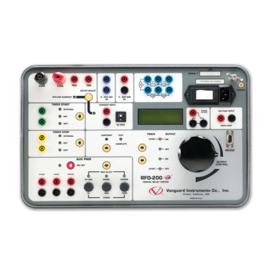
RFD-200 S3 USER’S MANUAL Controls and Indicators The RFD-200 S3’s controls and indicators are shown in Figure 1. The purpose of the controls and indicators may seem obvious, but users should become familiar with them before using the RFD-200 S3. Accidental misuse of the controls will usually cause no serious harm. Users should also be familiar with the safety summary found on the front page of this User’s Manual. -
Page 10: Functional Description
FUNCTIONAL DESCRIPTION RFD-200 S3 Auxiliary Power Supply The RFD-200 S3 provides 3 auxiliary power supplies (24 Vdc, 48 Vdc, and 125 Vdc) for powering electronic relays. Each power supply is fuse-protected. The power supply outputs are controlled by the auxiliary power supply button. -
Page 11: Control Switches
• START-OFF In this mode, the RFD-200 S3 turns off the voltage/current sources and starts the timer. The selected mode is indicated by an illuminated LED next to the label. The voltage and current source settings are controlled by the knob. -
Page 12: Timer Start And Timer Stop Inputs
NOTES 2. The dry contact input detects contact closed (shorted) or contact opened. 3. Applying a voltage to the timer “Dry” contact input may damage the RFD-200 S3 RFD-200 S3 Power Resistors Five power resistor connections are available on the RFD-200 S3. -
Page 13: Rfd-200 S3 External Voltage Input
LED must be illuminated in order to display the [EXT INPUT CURRENT] external current on the LCD screen. NOTE Auxiliary Contact Output The RFD-200 S3 features a set of NO/NC dry contacts (rated at 3A, 240 Vac/120 Vdc) that change state when a test is initiated. -
Page 14: Operating Procedures
Setting the Voltage or Current Source Use the steps below to set the voltage or current source: a. Ensure that the RFD-200 S3 output is off. When the unit is first turned on, the output will be off by default. -
Page 15: Setting The Rfd-200 S3 For A Time Delay Test
Setting the RFD-200 S3 for a Time Delay Test Use the steps below to measure an over-current relay time delay: a. Connect the RFD-200 S3 current source output across the relay coil as shown in Figure 2. b. Select INTERNAL for the... - Page 16 Select START-ON from the control mode area. The RFD-200 S3’s timer will start when it energizes the coil voltage, and it will stop when the relay dry contact changes state. The elapsed time and test current will be displayed during the test in seconds and cycles on the LCD screen: 15.7000S...
-
Page 17: Figure 2. Typical Over Current Relay Connection
REV 1 RFD-200 S3 USER’S MANUAL Figure 2. Typical Over Current Relay Connection... -
Page 18: Using The Rfd-200 S3'S Timer To Test Circuit Breaker Response Time
Using the RFD-200 S3’s Timer to Test Circuit Breaker Response Time Use the steps below to use the RFD-200 S3’s timer to measure the opening time of a circuit breaker. The timer will start when the RFD-200 S3 detects the voltage being applied to the circuit breaker trip coil. -
Page 19: Figure 3. Typical Circuit Breaker Timing Connection
REV 1 RFD-200 S3 USER’S MANUAL Figure 3. Typical Circuit Breaker Timing Connection... -
Page 20: Using The Rfd-200 S3'S Timer In Single Input Mode
Energize the relay coil to open the relay’s Normally Closed contact. The RFD-200 S3’s timer will start and the time will be displayed on the LCD screen. f. De-energize the relay coil to close the relay contact. The RFD-200 S3’s timer will stop and the time will be displayed on the LCD screen. - Page 21 REV 1 RFD-200 S3 USER’S MANUAL g. Press and hold the key for 2 seconds to return the RFD-200 [TIMER STOP ARROW] S3’s timer to dual input mode. The following screen will be displayed momentarily: Trigger Mode Set To Dual Input...
-
Page 22: Using The Rfd-200 S3 To Plot A Current Transformer Excitation Curve
Using the RFD-200 S3 to Plot a Current Transformer Excitation Curve Use the steps below to find the excitation curves of a current transformer (CT): a. Connect the RFD-200 S3 AC voltage source to the CT secondary winding in series with the external current input as shown in Figure 4. -
Page 23: Figure 4. Typical Ct Excitation Test Connection
REV 1 RFD-200 S3 USER’S MANUAL Figure 4. Typical CT Excitation Test Connection... -
Page 24: Using The Rfd-200 S3 To Measure Ct Primary And Secondary Currents
Using the RFD-200 S3 to Measure CT Primary and Secondary Currents Use the steps below to measure the CT primary and secondary currents with the RFD-200 S3: a. Connect the RFD-200 S3 current source through the CT primary current path as shown in Figure 5. - Page 25 REV 1 RFD-200 S3 USER’S MANUAL h. Select OFF from the control mode area.
-
Page 26: Figure 5. Typical Ct Turns Ratio Test Connection
RFD-200 S3 USER’S MANUAL REV 1 Figure 5. Typical CT Turns Ratio Test Connection... - Page 27 1520 S. Hellman Ave • Ontario, CA 91761 • USA Phone: 909-923-9390 • Fax: 909-923-9391 www.vanguard-instruments.com Copyright © 2012 by Vanguard Instruments Company, Inc. RFD-200 S3 User’s Manual • Revision 1 • July, 2012 • TA...
Need help?
Do you have a question about the RFD-200 S3 and is the answer not in the manual?
Questions and answers