Table of Contents
Advertisement
Quick Links
TECHNICAL MANUAL
TunnelTech 100 Series
TunnelTech 101
Visibility & Cold Smoke Detection
CODEL International Ltd.
Station Building, Station Road, Bakewell, Derbyshire DE45 1GE United Kingdom
t : +44 (0) 1629 814 351
f : +44 (0) 8700 566 307
e : codel@codel.co.uk
web : www.codel.co.uk
Issue : A
Rev. :
Date : 29/06/2015
Ref. : 100190
Advertisement
Table of Contents

Summary of Contents for CODEL TunnelTech 100 Series
- Page 1 TECHNICAL MANUAL TunnelTech 100 Series TunnelTech 101 Visibility & Cold Smoke Detection CODEL International Ltd. Station Building, Station Road, Bakewell, Derbyshire DE45 1GE United Kingdom t : +44 (0) 1629 814 351 f : +44 (0) 8700 566 307 e : codel@codel.co.uk web : www.codel.co.uk...
- Page 2 CODEL CODEL International Ltd is a UK company based in the heart of the Peak District National Park at Bakewell, Derbyshire. The company specialises in the design and manufacture of high-technology instrumentation for the monitoring of combustion processes and atmospheric pollutant emissions.
- Page 3 CODEL Technical Manual Issue : A Rev. : Date : 29/06/2015 Ref. : 100190...
-
Page 4: Table Of Contents
CODEL Technical Manual Contents 1. System Description 1.1. Air Quality Monitor – Visibility & Cold Smoke Detection 1.2. Measurement Elements 1.3. LED Control 1.4. Detector Element 1.5. Diagnostic Data 1.6. Calibration 1.7. Auto Zero 1.8. Temperature Measurement 2. Principles of Operation 2.1. - Page 5 CODEL Technical Manual Data Communication 6.1. Hardware Configuration 6.2. Address Numbers 7. List of Figures Appendix A Appendix B Appendix C Appendix D Issue : A Rev. : Date : 29/06/2015 Ref. : 100190...
- Page 7 CODEL Technical Manual IMPORTANT The warning signs (and meanings) shown below, are used throughout these instructions and are intended to ensure your safety while carrying out installation, operation and maintenance procedures. Please read these instructions fully before proceeding. Caution, risk of electric shock.
-
Page 9: System Description
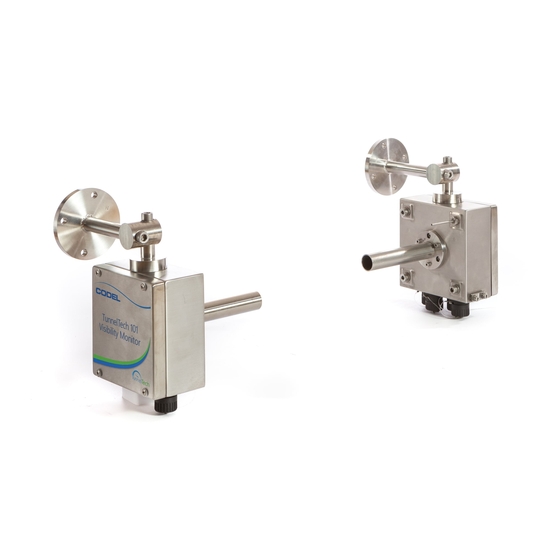
CODEL Technical Manual Page 1 System Description 1.1. TunnelTech 101 – Visibility measurement and Cold Smoke Detection The TunnelTech 101 system shown in Figure 1 uses visible light channels to measure visibility. The system consists of a transmitter and receiver, the transmitter projects a visible beam to a detector unit mounted 6m away in the receiver. -
Page 10: Measurement Elements
CODEL Technical Manual Page 2 1.2. Measurement Elements The visibility sensor produces a beam of light from a pulsed LED focused by a lens to a receiver unit mounted 6m away. An internal detector within the transmitter monitors the brightness of the emitted pulses of light. The transmitted beam is gathered by the receiver unit lens and focussed onto a receiving detector. -
Page 11: Auto Zero
CODEL Technical Manual Page 3 1.7. Auto Zero The measurement of opacity is dependent upon the optical surfaces of the instrument remaining clean. If the surfaces of the instrument lenses become contaminated it will reduce the intensity of the received light and increase the opacity measured value. -
Page 12: Principles Of Operation
CODEL Technical Manual Page 4 Principles of Operation Visibility and Cold Smoke Detection both rely on the amount of light obscuration within the tunnel atmosphere being determined. This obscuration is quantified by determining the visibility coefficient. A visibility sensor is programmed to measure low levels of visibility coefficient and thus light obscuration experienced during normal tunnel operation. -
Page 13: Specifications
CODEL Technical Manual Page 5 3. Specifications 3.1. General Construction Stainless Steel 316 Ti – other grades available on request. Safety & EMC shielded to comply with 2006/95/EEC EN61326-1:2006 & EN50270:2006 Ambient temperature C to +50 Dimensions Ø150mm x 81mm x 150mm... -
Page 14: Rs485 Interface
CODEL Technical Manual Page 6 3.3. RS485 Interface Power USB powered. PC Communications USB port. The serial USB RS485 interface is used as a temporary connection with the TunnelTech 101 during commissioning and for diagnostic communications. The operation function and operation of the interface are contained in Appendix A: Communication & RS485 Connection. -
Page 15: Installation
CODEL Technical Manual Page 7 4. Installation Be sure to observe all necessary safety precautions at all times during installation. All cable gland entry holes are drilled and tapped M20 x 1.5 and are fitted with blanking plugs. Cable glands are to be supplied by the customer according to the cables used during installation. -
Page 16: Connections
CODEL Technical Manual Page 8 4.2. Connections Wiring should only be undertaken by a qualified technician. The following electrical schematic (Figure 3) illustrates the connections for the system. A soldered connection is required between the cable and the corresponding plug or socket. - Page 17 CODEL Technical Manual Page 9 24V Power Transmitter Supply No connection Power Screen earth Socket Plug + Vout Receiver - Vout Rx/Tx Cable + Vout Rx/Tx - Vout No connection Cable Socket Plug No connection Socket Plug Current Contact Contact...
-
Page 18: Alignment Of Aqm Sensor
CODEL Technical Manual Page 10 4.3. Alignment of AQM Sensor Note – Align the transmitter and receiver prior to connecting power. The AQM transmitter and receiver units should be mounted horizontally and should be properly aligned for optimum performance. 4.3.1 Laser Adapter Assembly Mount the laser onto the adapter as shown in Figure 4. - Page 19 CODEL Technical Manual Page 11 Fit the assembly illustrated in Figure 4 onto the transmitter site tube. Make sure the plate of the adapter and the sight tube connect flush in the orientation shown below. Issue : A Rev. : Date : 29/06/2015 Ref.
- Page 20 CODEL Technical Manual Page 12 4.3.2 Horizontal Alignment of Transmitter 4.3.2.1 Slide the laser adaptor over the sight tube so that the laser pointer is at the top of the sight tube. Ensure that the holes in the adaptor flange locate onto the heads at the sight tube mounting bolts.
- Page 21 CODEL Technical Manual Page 13 4.3.2.2 Vertical Alignment Position the laser adaptor so that the laser pointer is located at the side of the mounting tube. Loosen screw 2 slightly to allow movement at the bracket. Position the laser line onto the centre of the receiver site tube then tighten screw 2, see Figure 6.
-
Page 22: Commissioning
CODEL Technical Manual Page 14 5. Commissioning 5.1. Alignment Ensure the transmitter and receiver are correctly aligned before connecting the power 5.2. Power Up Turn on the power and leave for 10 minutes. During this period the data will be invalid. The system will then automatically adjust the gain and set up the detector levels to the following;... - Page 23 CODEL Technical Manual Page 15 6. Data Communication 6.1. Hardware Configuration 6.1.1. System The PSU supplies power to the AQM. The current and relay outputs of the AQM communicate measurement data to the tunnels' DCS system. 6.2. Address Numbers Because communications between the interface and the sensor is serial digital, it is necessary for each sensor to be allocated an address number –...
- Page 24 CODEL Technical Manual Page 16 7. List of Figures Figure 1: TunnelTech 101 – AQM for visibility measurement and cold smoke detection. Figure 2: TunnelTech AQM – Mounting Holes Figure 3: Electrical Schematic Figure 4: Mounting Laser Figure 5: Horizontal Alignment...
- Page 25 CODEL Technical Manual Page 17 Appendix A: Communication & RS485 Connection The serial communication output of the TunnelTech 101 AQM RS485 is taken via the 4-way chassis plug. The following wiring schematic and photograph illustrate the connections. All AQMs are equipped with RS485 and will have labels indicating ‘RS485’. Connections in the plug are as...
- Page 26 Using standard MODBUS protocol function 03 allows a host to obtain the contents of one or more holding registers in the CODEL MODBUS TT Air Quality Monitor (AQM), this can be seen in appendix B. The request frame from the host (typically a DCS or SCADA) defines the relative address of the first holding register followed by the total number of consecutive registers to be read.
- Page 27 Page 19 Appendix B: TunnelTech AQM visibility Features TunnelTech AQM Data Validity Status: Control Register = 0x0100 (CODEL) - 0x0080 (Modbus) - Read Only Register High Byte: bit 0 : Power Up bit 1 : Zero Cal bit 2 : Auto Detector Setup...
- Page 28 CODEL Technical Manual Page 20 Command List: Control Register 0x019E (CODEL) - 0x00CF (Modbus) - Read and Write Register High byte: 0x00 : always 0x00 Low byte: (0x019F) 0x0A : AutoDetectorGainsCmd 0x0A //Auto Detector Gain Command 0x10 : CalibrateVisCmd 0x10...
- Page 29 CODEL Technical Manual Page 21 Appendix C: EEPROM Modbus map Modbus Address Description CODEL : Byte Address Decimal Hexadecimal 16256 3F80 0x7F00 16257 3F81 DtThreshold_EEPROM 0x7F02 16258 3F82 DrThreshold_EEPROM 0x7F04 16259 3F83 VizDetectorSmoothingFactor_EEPROM 0x7F06 16260 3F84 DtSaturation_EEPROM 0x7F08 16261 3F85...
- Page 30 CODEL Technical Manual Page 22 16297 3FA9 AutoZeroIncrementAmount_EEPROM 0x7F52 16298 3FAA AutoZeroDecrementAmount_EEPROM 0x7F54 3FAB_H AutoZeroIncrementCount_EEPROM 0x7F56 16299 3FAB_L AutoZeroDecrementCount_EEPROM 0x7F57 16300 3FAC AutoZeroMaxThreshold_EEPROM 0x7F58 16301 3FAD 0x7F5A 16302 3FAE 0x7F5C 16303 3FAF TxTemperatureSmoothingFactorEEPROM 0x7F5E 16304 3FB0 mA1DACSpan_EEPROM 0x7F60 16305 3FB1...
- Page 31 CODEL Technical Manual Page 23 3FCD_H 0x7F9A 16333 3FCD_L Alarm2SmoothingCoefficient_EEPROM 0x7F9B 3FCE_H Alarm2Direction_EEPROM 0x7F9C 16334 3FCE_L Alarm2Level_EEPROM 0x7F9D 3FCF_H 0x7F9E 16335 3FCF_L Alarm2DataType_EEPROM 0x7F9F Issue : A Rev. : Date : 29/06/2015 Ref. : 100190...
- Page 32 CODEL Technical Manual Page 24 Appendix D: Ram Modbus map Modbus Address Description CODEL : Byte Address Decimal Hexadecimal 0080_H AQMModeStatus_RAM 0x0100 0080_L AQMPerformanceStatus_RAM 0x0101 0081 0x0102 0082 0x0104 0083 0x0106 0084 0x0108 0085 0x010A 0086 0x010C 0087 0x010E 0088...
- Page 33 CODEL Technical Manual Page 25 00AC Vis_Km_1_RAM 0x0158 00AD 0x015A 00AE 0x015C 00AF Vis_Fault_Flag_RAM 0x015E 00B0 0x0160 00B1 0x0162 00B2 0x0164 00B3 Opacity_Inst_RAM 0x0166 00B4 0x0168 00B5 0x016A 00B6 Delta_Opacity_RAM 0x016C 00B7 0x016E 00B8 0x0170 00B9 0x0172 00BA 0x0174 00BB...
- Page 34 CODEL Technical Manual Page 26 00DC 0x01B8 00DD 0x01BA 00DE Tx_Temp_Remainder_RAM 0x01BC 00DF Air_Temp_Remainder_RAM 0x01BE 00E0_H AQMModeStatus_Copy_RAM 0x01C0 01E0_L AQMPerformanceStatus_Copy_RAM 0x01C1 00E1 0x01C2 00E2 Drx_Act_Inst_Copy_RAM 0x01C4 00E3 Dtx_Ref_Inst_Copy_RAM 0x01C6 00E4 Drx_Act_Smoothed_Copy_RAM 0x01C8 00E5 Dtx_Ref_Smoothed_Copy_RAM 0x01CA 00E6 SetCalVis_Smoothed_Copy_RAM 0x01CC 00E7 SetCalVis_Inst_Copy_RAM...
Need help?
Do you have a question about the TunnelTech 100 Series and is the answer not in the manual?
Questions and answers