
Related Manuals for Technoton MasterCAN Tool Lite

Summary of Contents for Technoton MasterCAN Tool Lite
- Page 1 CAN BUS IMITATOR/ANALYSER MasterCAN Tool Lite MasterCAN Tool Pro OPERATION MANUAL Version 3.0...
-
Page 2: Table Of Contents
2.3.3 Power Supply Connection ................28 2.3.4 Using CANCrocodile to connect to CAN Bus ........... 29 2.3.5 Connection to CAN Vehicle bus ..............30 2.3.6 Connection using S6 Technology ..............32 MasterCAN Tool CAN Bus Imitator/Analyzer. Operation manual. Version 3.0 © Technoton, 2018... - Page 3 3.3 Completion of work with Software and disconnection of the adapter ...... 48 4 Storage ....................... 49 5 Transportation ...................... 50 6 Utilization/re-cycling ..................... 51 Contacts ......................... 52 MasterCAN Tool CAN Bus Imitator/Analyzer. Operation manual. Version 3.0 © Technoton, 2018...
-
Page 4: Revision History
Editor Description of changes 02.2013 Basic version. 03.2015 Description of MasterCAN Tool Pro and MasterCAN Tool Lite models. The procedure for installation and use of MasterCAN Tool version 3.2 software. 03.2018 1) Modification of design and changes in the supplied accessories kit. -
Page 5: Structure Of External Links
Operation manual Part S6 Data Base S6 Website Part S6 Functional modules Page MasterCAN Tool Page CANCrocodile Page CAN j1939/S6 Telematics JV Technoton Website interface Part Software/Firmware Part Technical support YouTube Technoton Channel ORF 4 Website FMS-Standard Website MasterCAN Tool CAN Bus Imitator/Analyzer. Operation manual. Version 3.0... -
Page 6: Terms And Definitions
Parameters, Counters, Events. SPN can have a qualifier which allows qualification of parameter’s value (e.g. – Onboard power supply limit/Minimum). Onboard equipment (OE) — Telematics system elements, directly installed in Vehicle. MasterCAN Tool CAN Bus Imitator/Analyzer. Operation manual. Version 3.0 © Technoton, 2018... - Page 7 Uses input/output PGNs and settings PGNs. Unit is an element of vehicle on-board equipment compatible with S6 bus, which uses S6 Technology. MasterCAN Tool CAN Bus Imitator/Analyzer. Operation manual. Version 3.0 © Technoton, 2018...
-
Page 8: Introduction
The manual is intended for specialists familiar with the rules for performing repair and assembly works on Vehicles that have professional knowledge of electronic and electrical equipment of Vehicles. MasterCAN Tool CAN Bus Imitator/Analyzer. Operation manual. Version 3.0 © Technoton, 2018... - Page 9 Introduction MasterCAN Tool is represented by the following models: 1) MasterCAN Tool Lite — has basic functionality to receive data (PGN) of Vehicle bus (SAE J1939) or using Technology. 2) MasterCAN Tool Pro — has extended functionality to receive/transmit data (PGN) of CAN Vehicle bus (SAE J1939) or using S6 Technology.
-
Page 10: General Information And Technical Specifications
S6 Technology Figure 1 — Areas of MasterCAN Tool application * This feature is implemented only in MasterCAN Tool Pro. MasterCAN Tool CAN Bus Imitator/Analyzer. Operation manual. Version 3.0 © Technoton, 2018... -
Page 11: Functional Features
Selection of ID length 11 bit/29 bit in the mode of PGN raw data modeling. Indicator of CAN bus current load. * MasterCAN Tool Lite has a feature of saving/opening only for test messages. MasterCAN Tool CAN Bus Imitator/Analyzer. Operation manual. Version 3.0 © Technoton, 2018... -
Page 12: Delivery Set
7 S6 Mol Plug – 1 pc.; 8 USB A-B cable – 1 pc.; 9 Contactless reader CANCrocodile – 1 pc. Figure 2 — MasterCAN Tool delivery set MasterCAN Tool CAN Bus Imitator/Analyzer. Operation manual. Version 3.0 © Technoton, 2018... -
Page 13: Mastercan Tool Adapter
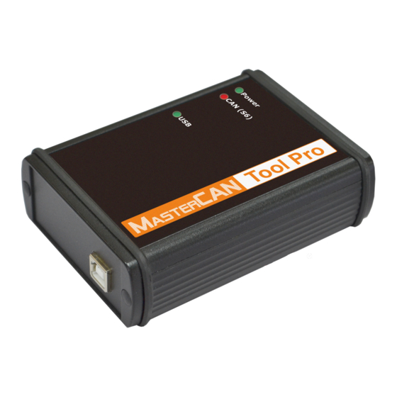
5 – green/red Power LED indicator for control of power supply; 6 – green/red CAN (S6) LED indicator for control of access to CAN bus or CAN j1939/S6 Telematic interface. Figure 3 —MasterCAN Tool external view and design MasterCAN Tool CAN Bus Imitator/Analyzer. Operation manual. Version 3.0 © Technoton, 2018... -
Page 14: Can J1939/S6 Digital Interface Characteristics
Power “+” voltage 9…45 V Brown Ground “-” — CANH Blue CAN HIGH Digital, SAE J1939 Standard CANL White CAN LOW Digital, KLIN Black K-Line ISO 14230 Standard MasterCAN Tool CAN Bus Imitator/Analyzer. Operation manual. Version 3.0 © Technoton, 2018... -
Page 15: Led-Indicators' Signal Description
No signal value is below the minimally allowed Data exchange via USB interface is in progress No data exchange via USB interface No signal USB interface is off MasterCAN Tool CAN Bus Imitator/Analyzer. Operation manual. Version 3.0 © Technoton, 2018... -
Page 16: Main Specifications
Current consumption at nominal supply voltage 12 V/24 V, 200/100 mA, not more than Operating ambient temperature, C -10…+60 Ingress protection rating IP40 Weight, kg, not more Overall dimensions, mm, not more figure 4 MasterCAN Tool CAN Bus Imitator/Analyzer. Operation manual. Version 3.0 © Technoton, 2018... -
Page 17: Overall Dimensions
General information and technical specifications / MasterCAN Tool Adapter/ Overall dimensions 1.4.5 Overall dimensions Figure 4 — MasterCAN Tool Adapter overall dimensions MasterCAN Tool CAN Bus Imitator/Analyzer. Operation manual. Version 3.0 © Technoton, 2018... -
Page 18: Cables
3 (for connector B) to connect to Digital, S6 connector of SAE J1939 the Adapter Standard D (for connector A) CANL White CAN LOW 4 (for connector B) MasterCAN Tool CAN Bus Imitator/Analyzer. Operation manual. Version 3.0 © Technoton, 2018... -
Page 19: Mastercan Tool Obd2 Cable
4 (for connector B) Connector B: to connect to S6 connector of the adapter 7 (for connector A) Digital, KLIN Black K-Line ISO 14230 5 (for connector B) Standard MasterCAN Tool CAN Bus Imitator/Analyzer. Operation manual. Version 3.0 © Technoton, 2018... -
Page 20: Mastercan Tool Cw Cable
Table 7 — Specifications of connectors of MasterCAN Tool CW cable Wire Signal Connector Connector Contact Pinout Marking Color Designation Parameters Number Brown Ground “-” — CANH Blue CAN HIGH Digital, SAE J1939 Standard CANL White CAN LOW MasterCAN Tool CAN Bus Imitator/Analyzer. Operation manual. Version 3.0 © Technoton, 2018... -
Page 21: S6 2-1 Mol Power T-Connector With Power Wire
S6 connector of CANH Blue CAN HIGH the adapter Digital, SAE J1939 Standard CANL White CAN LOW Connector C: spare one Digital, KLIN Black K-Line ISO 14230 Standard MasterCAN Tool CAN Bus Imitator/Analyzer. Operation manual. Version 3.0 © Technoton, 2018... -
Page 22: S6 Mol Plug
CAN HIGH Digital, SAE J1939 Standard CANL White CAN LOW R1 — inbuilt terminal resistor 120 Оhms. XP1 — connector to connect S6 Mol plug to S6 cable system. MasterCAN Tool CAN Bus Imitator/Analyzer. Operation manual. Version 3.0 © Technoton, 2018... -
Page 23: Usb A-B Cable
Figure 5 — USB A-B cable connectors USB A connector is connected to any vacant USB port of PC, while USB B is connected to the USB connector of the Adapter. MasterCAN Tool CAN Bus Imitator/Analyzer. Operation manual. Version 3.0 © Technoton, 2018... -
Page 24: Mastercan Tool Connecting And Configuring
screen resolution not less than 800x600; operating system (X32/X64) — Windows 7/10; special software (USB driver MasterCAN Tool software) need to be installed on PC. MasterCAN Tool CAN Bus Imitator/Analyzer. Operation manual. Version 3.0 © Technoton, 2018... -
Page 25: Software Installation
License Agreement and follow all the instructions of the installer. Note: To download the USB driver, you need to get registered. 2) MasterCAN Tool Software; its current version can be downloaded at the Technoton website at https://www.jv-technoton.com/ (Software Section). -
Page 26: Mastercan Tool Connecting
visible damages of the adapter body; connector and insulation damages of cables. Contact the supplier if any defects detected. MasterCAN Tool CAN Bus Imitator/Analyzer. Operation manual. Version 3.0 © Technoton, 2018... -
Page 27: Operation Restrictions
To avoid any MasterCAN Tool failures in communication between PC and the Adapter make sure there are no sources of electromagnetic interference close to the workplace (running electric motors, welding equipment, high-power transformers, power lines, etc.). MasterCAN Tool CAN Bus Imitator/Analyzer. Operation manual. Version 3.0 © Technoton, 2018... -
Page 28: Power Supply Connection
Terminals (ordered separately) are recommended for electrical connection to power supply wires (see figure 6). Figure 6 — Terminals for connecting to power supply wires MasterCAN Tool CAN Bus Imitator/Analyzer. Operation manual. Version 3.0 © Technoton, 2018... -
Page 29: Using Cancrocodile To Connect To Can Bus
3) The connection of power supply for CANCrocodile from the Vehicle onboard circuit is allowed using S6 2-1 Mol power T-connector from the supplied accessories kit. In this case disable External Power Source in the window Dialog. MasterCAN Tool CAN Bus Imitator/Analyzer. Operation manual. Version 3.0 © Technoton, 2018... -
Page 30: Connection To Can Vehicle Bus
Note — You can connect the Adapter to the PC USB port both before and after the power supply (Battery) is on and after the software is launched. a) contactless connection with CANCrocodile MasterCAN Tool CAN Bus Imitator/Analyzer. Operation manual. Version 3.0 © Technoton, 2018... - Page 31 MasterCAN Tool OBD2 cable d) contact connection with MasterCAN Tool J1939 cable Figure 9 — Examples of diagrams of MasterCAN Tool connection to the Vehicle CAN bus MasterCAN Tool CAN Bus Imitator/Analyzer. Operation manual. Version 3.0 © Technoton, 2018...
-
Page 32: Connection Using S6 Technology
Note — You can connect the Adapter to the PC USB port both before and after the power supply (Battery) is on and after the software is launched. Figure 10 — MasterCAN Tool connection diagram using S6 Technology MasterCAN Tool CAN Bus Imitator/Analyzer. Operation manual. Version 3.0 © Technoton, 2018... -
Page 33: Function Check
MasterCAN Tool is ready for operation from the moment the power supply is on (from the Vehicle onboard circuit or from the USB port of PC). table 3 for signal description of LED indicators located on the Adapter. MasterCAN Tool CAN Bus Imitator/Analyzer. Operation manual. Version 3.0 © Technoton, 2018... -
Page 34: Starting And Preliminary Configuration Of Software
Menu Adapter ID Tabs of operation modes Current parameters of CAN j1939/S6 interface Figure 13 — Software interface view after the establishment of a communication session with PC MasterCAN Tool CAN Bus Imitator/Analyzer. Operation manual. Version 3.0 © Technoton, 2018... - Page 35 5) In the area Sniffer mode you may enable/disable (disabled by default) the data reading mode in case of connection to CAN bus with CANCrocodile. In this case the PGN emulation mode does not work. MasterCAN Tool CAN Bus Imitator/Analyzer. Operation manual. Version 3.0 © Technoton, 2018...
- Page 36 In case you connect several MasterCAN Tool adapters to the PC, make use of the USB hub with external power supply to reduce the load on the PC USB ports. MasterCAN Tool CAN Bus Imitator/Analyzer. Operation manual. Version 3.0 © Technoton, 2018...
-
Page 37: Work With Mastercan Tool Software
WARNING: PGN emulation mode is available only in case you employ MasterCAN Tool Pro. In case you use MasterCAN Tool Lite, there is no Imitator tab in the Software window. 3) PGN raw data modeling mode (RAW tab) — generation and transmission test data packets to CAN bus (SAE J1939) or using S6 Technology with simultaneous monitoring all received PGN in real time by their ID or contents. -
Page 38: Work In The Pgn Monitoring Mode
Software is used. button is used for automatic alignment of the table columns width, in accordance with the text width. MasterCAN Tool CAN Bus Imitator/Analyzer. Operation manual. Version 3.0 © Technoton, 2018... - Page 39 (.log) from the window Open File. * You may also save/open the log file of the data log in the PGN emulation mode and the PGN raw data modeling mode MasterCAN Tool CAN Bus Imitator/Analyzer. Operation manual. Version 3.0 © Technoton, 2018...
-
Page 40: Work In The Pgn Emulation Mode
It complies with SAE J1939/71 Standard requirements; Telematics — a set of telematic PGN developed by Technoton which accumulates basic data on the Vehicle performance. It complies with SAE J1939/71 Standard requirements; ... - Page 41 Period — time period for message transmission. The range of changing values is from 0 to 65534 ms. If this period is 0 ms, the message is sent only upon request. MasterCAN Tool CAN Bus Imitator/Analyzer. Operation manual. Version 3.0 © Technoton, 2018...
- Page 42 PGN editor (for sets S6, FMS, FMSII, Telematics, J1939) b) DTC editor (for set DTC) c) Request editor (for set Service) Figure 17 — Examples of PGN editors in different sets MasterCAN Tool CAN Bus Imitator/Analyzer. Operation manual. Version 3.0 © Technoton, 2018...
- Page 43 To cancel the transmission of PGN to CAN bus or using S6 Technology, you should use button (see figure 18). button is used to delete the selected PGN. MasterCAN Tool CAN Bus Imitator/Analyzer. Operation manual. Version 3.0 © Technoton, 2018...
- Page 44 To open the earlier saved data file, open the menu File Open and from the window Open File select the necessary file (.toolProj). * You may also save/open the data file in the mode of modeling PGN raw data. MasterCAN Tool CAN Bus Imitator/Analyzer. Operation manual. Version 3.0 © Technoton, 2018...
-
Page 45: Work In The Mode Of Modeling Raw Data Of
RAW — to enter the contents of the data field of the modelled PGN in the hexadecimal presentation. To delete the test PGN, highlight it and press button. MasterCAN Tool CAN Bus Imitator/Analyzer. Operation manual. Version 3.0 © Technoton, 2018... - Page 46 Monitor window. button is designed for the user convenience during analyzing messages. It allows to keep permanently the latest received message in the bottom line of the Monitor window. MasterCAN Tool CAN Bus Imitator/Analyzer. Operation manual. Version 3.0 © Technoton, 2018...
-
Page 47: Adapter Firmware Update
Adapter operability. If another attempt is also unsuccessful, we recommend to contact Technoton technical support, e-mail: support@technoton.by. MasterCAN Tool CAN Bus Imitator/Analyzer. Operation manual. Version 3.0 © Technoton, 2018... -
Page 48: Completion Of Work With Software And Disconnection Of The Adapter
3) Disconnect the Adapter power supply from the Vehicle onboard circuit. 4) Disconnect S6 connector of the Adapter from the Vehicle bus or from CAN j1939/S6 Telematic interface. MasterCAN Tool CAN Bus Imitator/Analyzer. Operation manual. Version 3.0 © Technoton, 2018... -
Page 49: Storage
Do not store MasterCAN Tool in the same room with substances that cause metal corrosion and/or contain aggressive impurities. MasterCAN Tool shelf life must not exceed 24 months. MasterCAN Tool CAN Bus Imitator/Analyzer. Operation manual. Version 3.0 © Technoton, 2018... -
Page 50: Transportation
When transporting by air, MasterCAN Tool must be stored in heated pressurized compartments. Air environment in transportation compartments should not contain acid, alkaline and other aggressive impurities. Shipping containers with packed MasterCAN Tool should be sealed. MasterCAN Tool CAN Bus Imitator/Analyzer. Operation manual. Version 3.0 © Technoton, 2018... -
Page 51: Utilization/Re-Cycling
MasterCAN Tool does not contain precious metals in amount that should be recorded. MasterCAN Tool CAN Bus Imitator/Analyzer. Operation manual. Version 3.0 © Technoton, 2018... -
Page 52: Contacts
Contacts Contacts Manufacturer Tel/fax: +375 17 240-39-73 http://s6.jv-technoton.com/ E-mail: marketing@technoton.by Technical support E-mail: support@technoton.by MasterCAN Tool CAN Bus Imitator/Analyzer. Operation manual. Version 3.0 © Technoton, 2018...
Need help?
Do you have a question about the MasterCAN Tool Lite and is the answer not in the manual?
Questions and answers